
Heat-conduction oil heating device for heat-conduction oil furnace

A heat-conducting oil furnace and heating device technology, which is applied in the field of heat-conducting oil heating devices of heat-conducting oil furnaces, can solve problems such as damage to heat-conducting oil, damage to heat-conducting oil delivery pipelines, and equipment damage, so as to reduce the probability of pollution and facilitate worker monitoring , the effect of reducing operating costs

Pending Publication Date: 2020-11-06
QINGYUAN JINGWANG ENVIRONMENTAL PROTECTION EQUIP
View PDF0 Cites 0 Cited by
  • Summary
  • Abstract
  • Description
  • Claims
  • Application Information

AI Technical Summary

Problems solved by technology

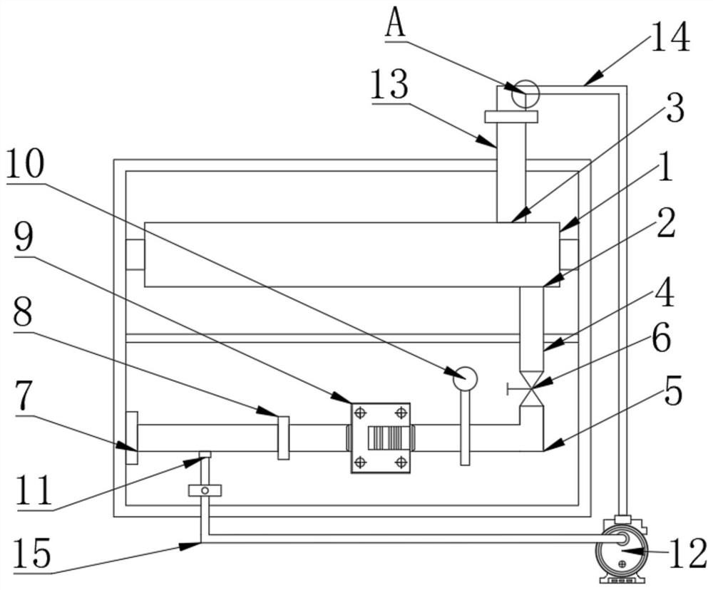
[0004] The purpose of the present invention is to provide a heat-conducting oil heating device for a heat-conducting oil furnace to solve the problem of hydrochloric acid entering the heat-conducting oil pipeline and then entering the heat-conducting oil boiler due to the damage of the seal of the graphite heat exchanger in the existing heating system , damage the heat transfer oil pipeline, heat transfer oil furnace and other equipment, and also damage the heat transfer oil. Every time a series of acid accidents occur, all the heat transfer oil has to be replaced, which causes the problem of equipment damage over time.

Method used


Image

  • Heat-conduction oil heating device for heat-conduction oil furnace
  • Heat-conduction oil heating device for heat-conduction oil furnace

Examples


Embodiment Construction

[0015] In order to make the technical means, creative features, goals and effects achieved by the present invention easy to understand, the present invention will be further elaborated below in conjunction with the accompanying drawings and specific implementation methods.

[0016] In the description of the present invention, it should be noted that the terms "upper", "lower", "inner", "outer", "front end", "rear end", "both ends", "one end", "another end" The orientation or positional relationship indicated by etc. is based on the orientation or positional relationship shown in the drawings, and is only for the convenience of describing the present invention and simplifying the description, rather than indicating or implying that the referred device or element must have a specific orientation, use a specific Azimuth configuration and operation, therefore, should not be construed as limiting the invention. In addition, the terms "first" and "second" are used for descriptive pu...


PUM


Abstract

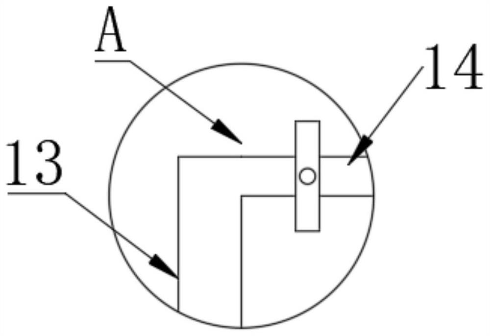
The invention discloses a heat-conduction oil heating device for a heat-conduction oil furnace. The heat-conduction oil heating device comprises the heat-conduction oil furnace, a first interface is formed in the lower side of the heat-conduction oil furnace, a second interface is formed in the upper side of the heat-conduction oil furnace, a first heat-conduction oil pipe is arranged at the end,away from the heat-conduction oil furnace, of the first interface, the bottom end of the first heat-conduction oil pipe is fixedly connected with a second heat-conduction oil pipe, and a stop valve isarranged between the first heat-conduction oil pipe and the second heat-conduction oil pipe. A first oil injection hole is formed in the left side of the second heat-conduction oil pipe, an oil filter is arranged in the middle of the second heat-conduction oil pipe, and a graphite heat exchanger is arranged on the right side of the oil filter. By means of the heat-conduction oil heating device, hydrochloric acid is prevented from being plunged into the heat-conduction oil furnace after sealing of the graphite heat exchanger is damaged, it is convenient for a worker to monitor by arranging a PH meter, and the heat-conduction oil furnace is better protected. If an acid-connecting accident happens, only the heat-conduction oil in the second heat-conduction oil pipe is contaminated, the probability that the heat-conduction oil in the heat-conduction oil furnace is contaminated is reduced, and the cost loss is reduced.

Description

technical field [0001] The invention relates to the technical field of heat-conducting oil furnace heating equipment, in particular to a heat-conducting oil heating device for a heat-conducting oil furnace. Background technique [0002] The heat conduction oil furnace is a new type of boiler with low pressure and high temperature working characteristics. The heat conduction oil is used as the working medium, and the heat oil circulation pump is used to force the medium to circulate in the liquid phase, and the heat energy is delivered to the heat consuming equipment and then returned to the furnace for reheating. Heating, it can obtain high working temperature under low working pressure, and can carry out high-precision control of medium operation, high heat utilization rate of the system, convenient operation and maintenance, is a safe, efficient and energy-saving ideal first-choice heating equipment . [0003] In our existing heating system, due to the damage of the seal ...

Claims


Application Information

Patent Timeline
IPC IPC(8): F24H7/02F24H9/20F24H9/00
CPCF24H7/02F24H9/0005F24H9/0042F24H9/2007
Inventor 李璐曹坤王爱武靳景伟
Owner QINGYUAN JINGWANG ENVIRONMENTAL PROTECTION EQUIP
Learn More