Double-material-barrel type capillary rheometer

A capillary rheometer and capillary technology, applied in the field of rheology testing, can solve problems such as single structure design, unfavorable use, equipment damage, etc., and achieve the effect of obvious dissolution effect, wide coverage area and strong heat dissipation performance

Pending Publication Date: 2020-11-06
上海毅兴塑胶原料有限公司
View PDF9 Cites 0 Cited by
  • Summary
  • Abstract
  • Description
  • Claims
  • Application Information

AI Technical Summary

Problems solved by technology

[0005] The present invention aims to solve the problem that the existing double-barrel capillary rheometer has a single structure design, the heating stability is not high during operation, so that the material cannot be completely dissolved, and the heat dissipation performance of the existing double-barrel capillary rheometer is not strong. Because the inside of the chassis needs to be heated at high temperature, and the machine cannot effectively transfer the heat to the inside of the chassis, the chassis will cause damage to the internal equipment of the machine due to high temperature, shortening the service life of the machine, which is not conducive to actual use. A double-material Barrel-type capillary rheometer, by setting the fixed block, fan, heating plate, pressure relief valve and capillary, the structure of the device is stable, and the high temperature inside the machine can be effectively maintained when the material is dissolved, so that the material can be fully dissolved. And this device has strong heat dissipation performance. When the machine needs high temperature for a long time to dissolve, the equipment inside the machine will dissipate heat, which solves the problem of damage to the equipment inside the machine due to long-term high temperature.

Method used


Image

  • Double-material-barrel type capillary rheometer
  • Double-material-barrel type capillary rheometer
  • Double-material-barrel type capillary rheometer

Examples


Embodiment

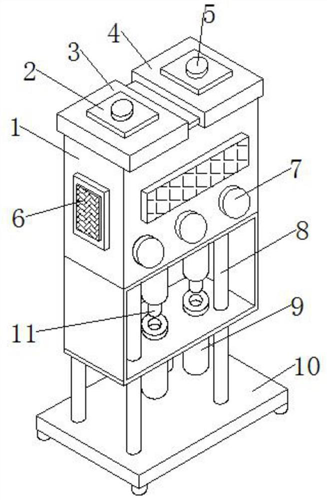
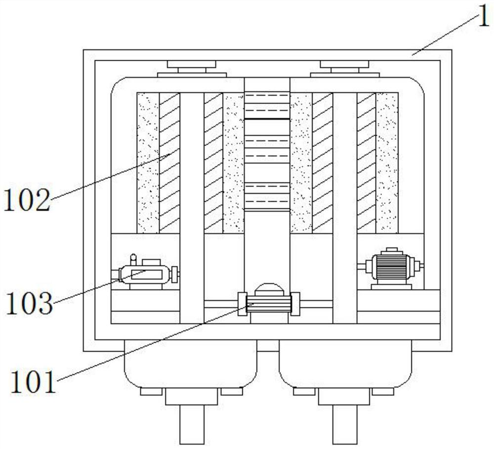
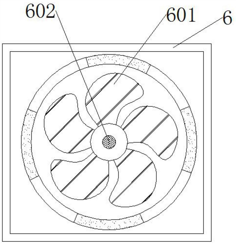
[0025] refer to Figure 1-4 ,

[0026] A double-barrel capillary rheometer provided in this embodiment includes a case 1, a cover 2 and a barrel 3, the cover 2 is located at the top of the case 1, and the cover 2 is movably connected with the case 1, and the left end of the inside of the case 1 A material barrel 3 is provided, and the a material barrel 3 is fixedly connected with the chassis 1, and the b material barrel 4 is provided at the inner right end of the chassis 1, and the b material barrel 4 is fixedly connected with the chassis 1, and the inside of the chassis 1 is provided with a pressure relief valve 101, And the pressure relief valve 101 is fixedly connected with the cabinet 1, the inside of the cabinet 1 is provided with a heating plate 102, and the heating plate 102 is fixedly connected with the cabinet 1, the inside of the cabinet 1 is provided with a heater 103, and the heater 103 is fixedly connected with the cabinet 1, the machine The upper end of the cove...


PUM


Abstract

The invention provides a double-material-barrel type capillary rheometer, and belongs to the technical field of rheology testing. The capillary rheometer comprises a machine box, a machine cover and amaterial barrel a, wherein the machine cover is located at the top of the machine box and movably connected with the machine box, the material barrel a is arranged at the left end of the inner side of the machine box and the material barrel a is fixedly connected with the machine box; the material barrel b is arranged at the right end of the inner side of the machine box and fixedly connected with the machine box; a pressure release valve is arranged in the machine box and fixedly connected with the machine box; and a heating plate is arranged in the machine box. The double-material-barrel type capillary rheometer is stable in structure; when the device is actually used, and when the materials are dissolved, the high temperature in the machine can be effectively maintained, and the materials can be fully dissolved; and the device is high in heat dissipation performance, equipment in the machine can dissipate heat of the machine due to the fact that the machine needs to be dissolved athigh temperature for a long time during work, and the problem that the equipment in the machine is damaged due to the fact that the machine is at high temperature for a long time is solved.

Description

technical field [0001] The invention relates to the technical field of rheology testing, in particular to a double-barrel capillary rheometer. Background technique [0002] Capillary rheometer can be used to measure the fluidity and solidification speed of thermosetting materials, draw the stress change curve and plasticizing curve of thermoplastic materials, measure the temperature of softening point, melting point and flow point, and measure the viscosity and Viscous flow activation can also study the process conditions of melt spinning. The traditional capillary rheometer, whether it is a single-tube capillary rheometer or a double-tube capillary rheometer that has appeared in recent years, is a one-way extrusion , that is, feed from the upper end of the barrel, and the material is extruded through the capillary outlet. In the next experiment, it is necessary to re-feed from the barrel and extrude from the capillary outlet again. [0003] However, the existing double-bar...

Claims


Application Information

Patent Timeline
Patent Type & Authority Applications(China)
IPC IPC(8): G01N11/04
CPCG01N11/04
Inventor 刘雋瑜阚小明许金时
Owner 上海毅兴塑胶原料有限公司
Why Eureka
Try Eureka