
Ultra-wideband low-scattering metamaterial based on combination of wave-absorbing material and metasurface

A technology of absorbing materials and metamaterials, applied in electrical components, antennas, etc., can solve the problems of narrow 10dBRCS reduced bandwidth, limited reduced bandwidth, poor antenna scattering performance, etc. Effect

Active Publication Date: 2020-11-06
XIDIAN UNIV
View PDF23 Cites 8 Cited by
  • Summary
  • Abstract
  • Description
  • Claims
  • Application Information

AI Technical Summary

Problems solved by technology

Among them, on the basis of the first measure, a supersurface absorber can be designed by using a large number of lumped resistors or resistor sheets, but the 10dB RCS reduction bandwidth is very narrow; the second measure is to first use the ideal electric conductor PEC and the artificial magnetic conductor The 180-degree phase difference of AMC realizes the reduction of narrow-band radar scattering cross-section, and then designs several metasurfaces composed of different elements with a certain phase difference, such as phase gradient metasurface, encoding metasurface and polarization rotating reflective surface, to achieve broadband The radar cross section is reduced, but its 10dB RCS reduction bandwidth is also very narrow
Therefore, the metasurface based on the above two measures to achieve 10dB RCS reduction bandwidth is very limited, resulting in poor scattering performance of the antenna

Method used


Image

  • Ultra-wideband low-scattering metamaterial based on combination of wave-absorbing material and metasurface
  • Ultra-wideband low-scattering metamaterial based on combination of wave-absorbing material and metasurface
  • Ultra-wideband low-scattering metamaterial based on combination of wave-absorbing material and metasurface

Examples


Embodiment Construction

[0029] Below in conjunction with accompanying drawing and specific embodiment, the present invention is described in further detail:

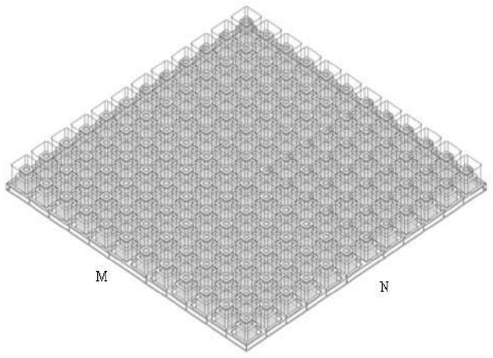
[0030] refer to figure 1 , this example is formed by splicing M*N low-scattering metamaterial units in a checkerboard arrangement, where M≥2, N≥2, and M and N are positive integers.

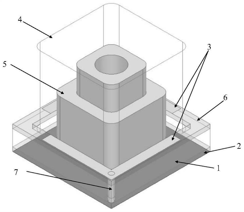
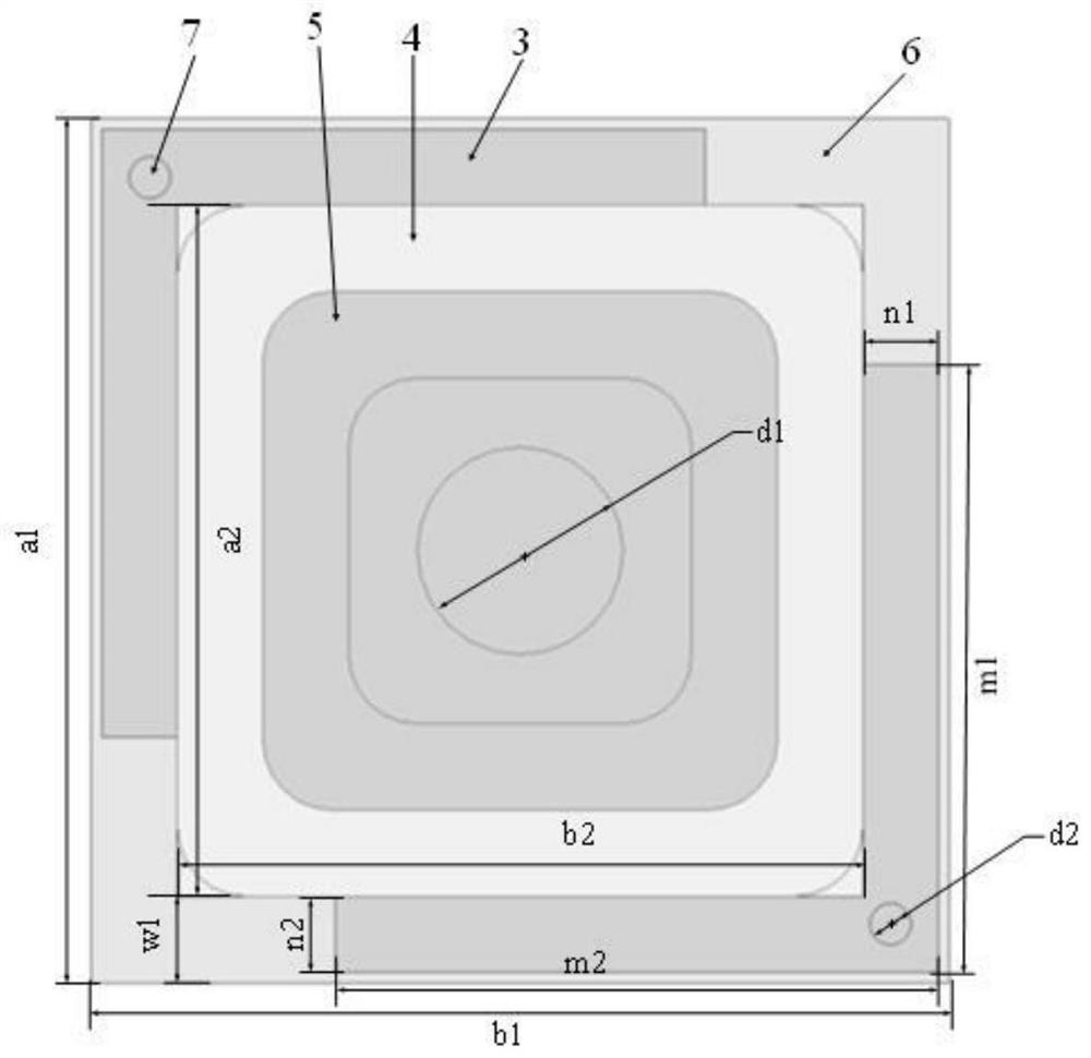
[0031] refer to figure 2 , image 3 with Figure 4 , each metamaterial unit includes a metal floor 1 , a lower dielectric substrate 2 , a pair of L-shaped metal patches 3 , a safety glass container 4 , an upper dielectric substrate 6 and metallized vias 7 .

[0032] The lower surface of the lower dielectric substrate 2 is closely attached to the upper surface of the metal floor 1; the safety glass container 4 is fixed on the upper surface of the lower dielectric substrate 2, the safety glass container is filled with an aqueous solution 5, and the safety glass container 4 forms a water absorbing wave material unit;

[0033] The upper dielectric substrate 6 is...


PUM

PropertyMeasurementUnit
Lengthaaaaaaaaaa
Lengthaaaaaaaaaa
Widthaaaaaaaaaa

Abstract

The invention discloses an ultra-wideband low-scattering metamaterial based on combination of a wave-absorbing material and a metasurface. The ultra-wideband low-scattering metamaterial mainly solvesthe problem that the scattering cross section reduction frequency band of an existing 10dB radar is narrow. The metamaterial is formed by splicing M*N low-scattering metamaterial units according to achessboard type arrangement mode, and each unit comprises a metal floor (1), a lower dielectric substrate (2) and a pair of L-shaped metal patches (3); the lower surface of the lower dielectric substrate is clung to the upper surface of the metal floor, a safety glass container (4) is arranged on the upper surface of the lower dielectric substrate, and an aqueous solution (5) is filled in the safety glass container to form a water wave-absorbing material unit with the safety glass container; an upper dielectric substrate (6) is arranged right above the lower dielectric substrate, and a pair ofL-shaped metal patches are printed on the upper surface of the upper dielectric substrate and are connected with the metal floor through metallized via holes (7) to form a polarization rotation metasurface structure unit. According to the invention, the reduction frequency band is improved, and the radar scattering cross section reduction in the whole ultra-wide frequency band can be realized.

Description

technical field [0001] The invention belongs to the technical field of microwave materials, in particular to a low-scattering metamaterial, which can be used to reduce the radar scattering cross section of an antenna. Background technique [0002] In the field of radar antennas, the key to improving the scattering characteristics is how to reduce the radar cross section, and the radar cross section is the most basic parameter in the scattering characteristics. It refers to a measure of the return power of a target in a given direction under the illumination of a plane wave. [0003] The antenna is a special kind of scatterer. Its scattering includes two parts: one part is the scattering field of the structural mode item that has nothing to do with the load of the scattering antenna. It is the scattering field when the antenna is connected to a matching load. Its scattering mechanism is the same as that of an ordinary scatterer. ; the other part is the scattered field of the ...

Claims


Application Information

Patent Timeline
IPC IPC(8): H01Q15/00H01Q17/00H01Q15/24
CPCH01Q15/0086H01Q15/24H01Q17/00
Inventor 贾永涛刘华骏刘英王兴
Owner XIDIAN UNIV
Learn More