A circuit for fast gain calibration of digital-to-time converter of phase locked loop

A digital time and gain calibration technology, which is applied to the automatic control of electrical components and power, can solve the problems of limited error information and slow calibration speed, and achieve the effect of improving the calibration speed and accelerating the LMS calibration process

Active Publication Date: 2020-11-06
TSINGHUA UNIV
View PDF5 Cites 3 Cited by
  • Summary
  • Abstract
  • Description
  • Claims
  • Application Information

AI Technical Summary

Problems solved by technology

Usually in actual implementation, only binary error information such as lead/lag is used to represent, so the error information provided t

Method used


Image

  • A circuit for fast gain calibration of digital-to-time converter of phase locked loop
  • A circuit for fast gain calibration of digital-to-time converter of phase locked loop
  • A circuit for fast gain calibration of digital-to-time converter of phase locked loop

Examples


Embodiment Construction

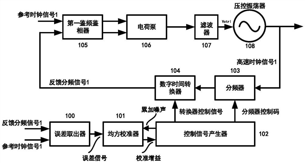
[0013] The circuit that the present invention proposes carries out fast gain calibration to the digital time converter of phase-locked loop, its structure is as follows figure 1 shown, including:

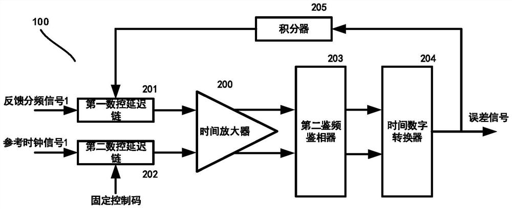
[0014] Error extractor 100, mean square calibrator 101, control signal generator 102, frequency divider 103, digital time converter 104, first frequency and phase detector 105, charge pump 106, filter 107 and voltage controlled oscillator 108 ; Wherein, the output end of described error extractor 100 is connected with the error input end of described mean square calibrator 101; The noise input terminal is connected, the output terminal of the mean square calibrator 101 is connected with the calibration gain input terminal of the control signal generator 102, and the converter control signal output terminal of the control signal generator 102 is connected with the digital time converter 104. The input end is connected, the frequency division control code output end of the control si...


PUM


Abstract

The invention relates to a circuit for fast gain calibration of a digital-to-time converter of a phase-locked loop, and belongs to the technical field of analog integrated circuit design. The circuitis composed of a digital time converter, an error measurement module, a gain calibration module, a digital controller, a phase frequency detector, a charge pump, a voltage-controlled oscillator and afrequency divider. According to the circuit provided by the invention, the error measurer can provide a multi-bit error signal for the gain calibration module; the time-to-digital converter is set tooutput an error signal represented by a 4-bit binary system. On one hand, the error signal serves as the input of the integrator; on the other hand, the output is used as an error extractor; error signals can represent leading/backward states of two input signals of the time amplifier. In addition, the size of the specific leading/lagging quantity can be represented, which means that more information is provided for the LMS calibration module, thereby accelerating the LMS calibration process of the analog phase-locked loop, and greatly improving the calibration speed of the analog phase-lockedloop.

Description

technical field [0001] The invention relates to a circuit for fast gain calibration of a digital time converter of a phase-locked loop, belonging to the technical field of analog integrated circuit design. Background technique [0002] A phase-locked loop (hereinafter referred to as PLL) is the core circuit in various communication and clock chips. Spectral noise, jitter, spurious and other indicators of its output signal are very critical and will directly affect system performance. Fractional frequency-division phase-locked loop is an important type of phase-locked loop. It can achieve the effect that the output frequency is a non-integer multiple of the phase detection frequency by quickly switching the frequency division ratio of the feedback frequency divider. In this way, in a fixed channel The width allows the use of a high reference frequency, which reduces the in-band noise and improves the integral jitter performance of the phase-locked loop. However, if you want ...

Claims


Application Information

Patent Timeline
IPC IPC(8): H03L7/08H03L7/107H03L7/197
CPCH03L7/08H03L7/107H03L7/197
Inventor 张雷袁泽心
Owner TSINGHUA UNIV
Why Eureka
Try Eureka