MISO system downlink secrecy rate optimization method by means of intelligent reflection surface
What is AI technical title?
AI technical title is built by Patsnap AI team. It summarizes the technical point description of the patent document.
A reflective surface, rate optimization technology, applied in transmission systems, radio transmission systems, diversity/multi-antenna systems, etc., can solve problems such as high hardware complexity and cost, high energy consumption, and high complexity
Active Publication Date: 2020-11-06
SOUTHEAST UNIV
View PDF3 Cites 26 Cited by
Summary
Abstract
Description
Claims
Application Information
AI Technical Summary
This helps you quickly interpret patents by identifying the three key elements:
Problems solved by technology
Method used
Benefits of technology
Problems solved by technology
However, the above solutions have their inherent defects in the actual deployment process: such as high energy consumption, high hardware complexity and cost, etc.
In the block coordinate descentalgorithm, the phase offset generated by each reflection unit is regarded as an independent unit, and the sequential optimization method is adopted in the optimization process, and only the phase offset introduced by one reflection unit is updated at a time, so the algorithm converges The speed is slow, and it is not suitable for large-scale IRS; the parallel optimizationalgorithm can optimize the phase offset introduced by all reflection units in one update process, and the algorithm converges quickly, but the existing ones based on Charnes-Cooper transformation and semidefinite The algorithm of planning (Semidefinite Relaxation, SDR) will introduce too high complexity, so the practical application value is low
Method used
Image
Click on the blue label to locate the original text in one second.
Reading with bidirectional positioning of images and text.
Examples
Embodiment 1
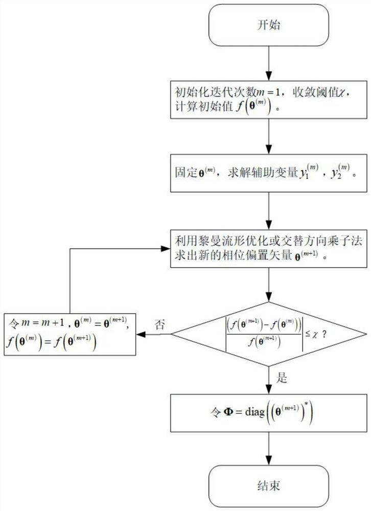
[0101] Step S4.3.1, set iteration times k=0, convergence threshold δ, initial point θ k ∈CCM, where CCM is a complex circular manifold, namely Initial search direction ξ k is the point θ k function f 3 (θ)=θ H Uθ-θ H γ-γ H The negative Riemannian gradient of θ, namely
[0102]function 3 at point θ k The calculation method of the Riemann gradient is as follows:
[0103]
[0104] Among them, ⊙ represents Hadamard product, represents the function f 3 at point θ k The Euclidean gradient at is calculated as follows:
[0105]
[0106] Step S4.3.2, according to the backtrackingline search to determine along the direction ξ k The search step size μ k .
[0126] Step A4.3.2, give the Lagrangian function of the objective function:
[0127]
[0128] in For the equality constraints |θ r |=1, The Lagrange multiplier of , ψ(θ) is an indicator function, when the unit module constraint is established, the value of ψ(θ) is 0, and when the unit module constraint is not established, the value of ψ(θ) is ∞;
[0129] Step A4.3.3, using the alternate direction multiplier method, update the parameters in the following order until the objective function value converges in step A4.3.1:
[0130]
[0131] Thus we can get θ (m+1) = θ (n+1) ;
[0132] Step A4.3.4, when When, Φ (i) =diag((θ (m+1) ) * );when , let m=m+1, and repeat steps A4.3.2-A4.3.4.
[0133] Step...
PUM
Abstract
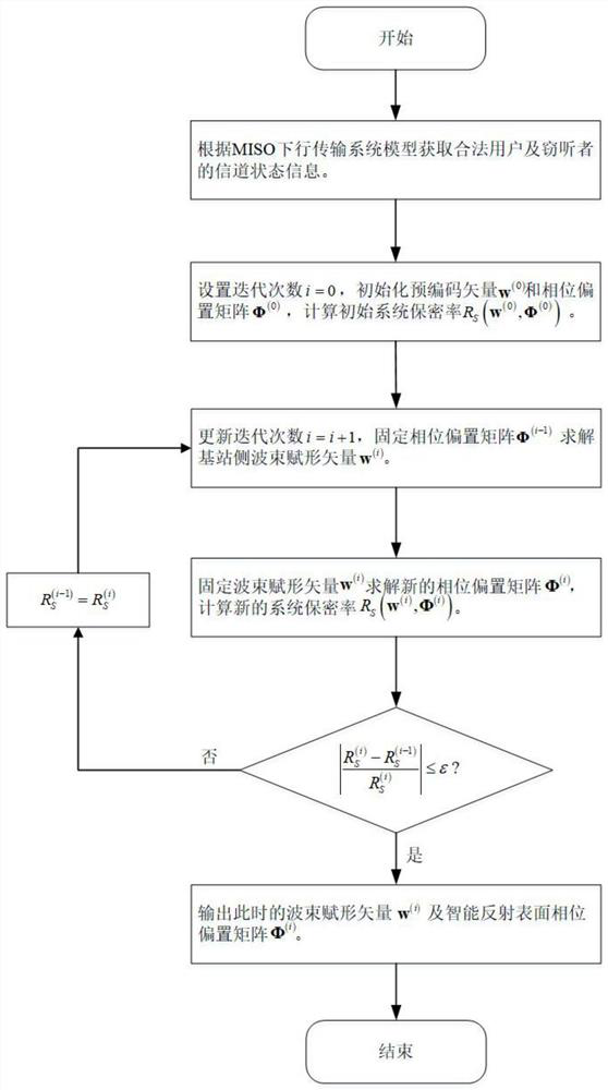
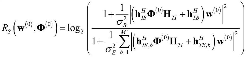
The invention discloses an MISO system downlink secrecy rate optimization method by means of an intelligent reflection surface. The MISO system downlink secrecy rate optimization method comprises thefollowing steps of: acquiring channel state information of legal users and eavesdroppers; fixing an intelligent reflection surface phase offset matrix, and calculating an optimal base station side beam-forming vector; fixing the optimized beam-forming vector to obtain a local optimal solution of the intelligent reflection surface phase offset matrix; and repeating the alternating optimization process until convergence, and outputting a beam-forming vector and a phase offset matrix obtained by the last iteration. By jointly designing the base station side beam-forming vector and the intelligentreflection surface phase offset matrix, the system secrecy rate is maximized, the calculation complexity can be effectively reduced, the number of iterations can be reduced, the operation time is saved, and the method has practicability and high efficiency in a multi-antenna secrecy transmission system.
Description
technical field [0001] The invention relates to the technical field of wireless communication, and mainly relates to a method for optimizing the downlink secrecy rate of a MISO system by means of an intelligent reflective surface. Background technique [0002] The system secrecy rate is an important index to measure the security performance of the physical layer of the wireless communication system, so improving the system secrecy rate has become a key issue in the field of wireless communication. In recent years, scholars have proposed a variety of solutions to solve this problem, such as: adding artificial noise to the beamforming vector, using joint blocking techniques, etc. However, the above-mentioned solutions all have their inherent defects in the actual deployment process: such as high energy consumption, high hardware complexity and cost, and so on. [0003] With the rapid development of synthetic materials and RF MEMS, Intelligent Reflecting Surface (IRS) is expec...
Claims
Application Information
Patent Timeline
Application Date:The date an application was filed.
Publication Date:The date a patent or application was officially published.
First Publication Date:The earliest publication date of a patent with the same application number.
Issue Date:Publication date of the patent grant document.
PCT Entry Date:The Entry date of PCT National Phase.
Estimated Expiry Date:The statutory expiry date of a patent right according to the Patent Law, and it is the longest term of protection that the patent right can achieve without the termination of the patent right due to other reasons(Term extension factor has been taken into account ).
Invalid Date:Actual expiry date is based on effective date or publication date of legal transaction data of invalid patent.

