Equipment for automatic filling of canned industrial butter

An automatic filling and canning technology, which is applied in packaging and other directions, can solve the problem of slow filling speed of butter, achieve the effect of fast filling speed and improve production efficiency

Active Publication Date: 2020-11-10
广西富勒星科技有限责任公司
View PDF9 Cites 11 Cited by
  • Summary
  • Abstract
  • Description
  • Claims
  • Application Information

AI Technical Summary

Problems solved by technology

[0005]In order to overcome the shortcomings of the need to manually transport the empty jars and cap them during the butter filling process, which makes the filling speed of the butter slower, the technical problem of the present invention is: Provide an automatic filling canned industrial butter equipment that can quickly fill butter, and can cap the jars that have been filled with butter at the same time

Method used


Image

  • Equipment for automatic filling of canned industrial butter
  • Equipment for automatic filling of canned industrial butter
  • Equipment for automatic filling of canned industrial butter

Examples


Embodiment 1

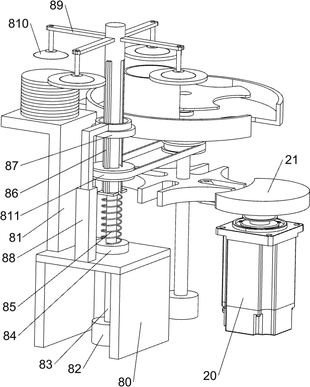
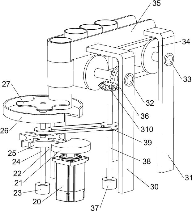
[0021] A device for automatically filling canned industrial butter, such as Figure 1-3 As shown, it includes a base plate 1, a rotating mechanism 2, a feeding mechanism 3, a material box 4, a discharge pipe 5, a rotating plate 6, a handle 7 and a capping mechanism 8, and a rotating mechanism 2 is provided on the left front side of the upper part of the base plate. 1 is provided with a blanking mechanism 3 on the right rear side of the upper part, a material box 4 is provided on the left rear side of the upper part of the bottom plate 1, a rotating plate 6 is provided on the upper part of the material box 4, a handle 7 is provided on the upper right side of the rotating plate 6, and the rotating plate 6 is embedded Type is provided with discharge pipe 5, and base plate 1 upper left middle is provided with gland mechanism 8.

[0022] When the user needs to fill the empty tank with butter, he can use this device. First, open the rotating plate 6 on the material box 4 through the...

Embodiment 2

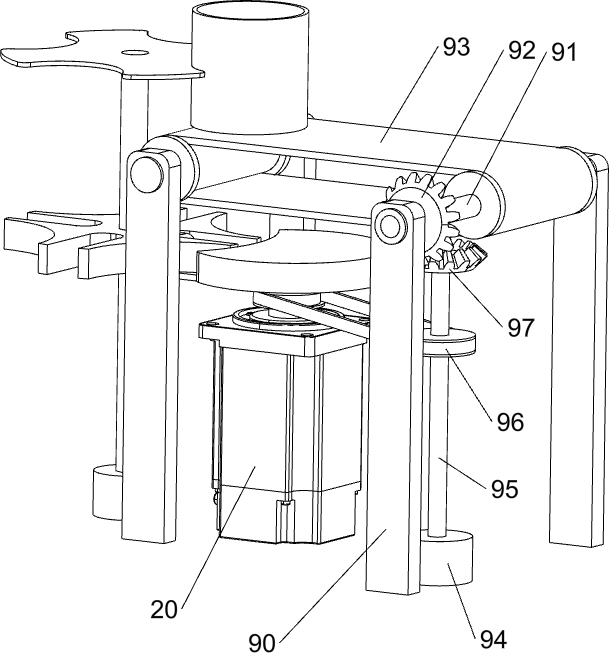
[0030] On the basis of Example 1, such as figure 1 and Figure 4 As shown, a feeding mechanism 9 is also included. The upper left front side of the bottom plate 1 is provided with a feeding mechanism 9. The feeding mechanism 9 includes a third support frame 90, a sixth rotating shaft 91, a third bevel gear 92, a fourth pulley assembly 93, and a third pulley assembly. Seven bearing blocks 94, the seventh rotating shaft 95, the fifth pulley assembly 96 and the fourth bevel gear 97, four third support frames 90 are uniformly arranged on the left front side of the upper part of the bottom plate 1, and the two third support frames 90 on the front side are connected with the rear The sixth rotating shaft 91 is respectively rotated between the two third supporting frames 90 on the side, the fourth pulley assembly 93 is wound between the sixth rotating shaft 91 on the front and rear sides, and the left part of the sixth rotating shaft 91 on the front side is provided with The third b...


PUM


Abstract

The invention relates to filling equipment, in particular to equipment for automatic filling of canned industrial butter. The technical problem to be solved by the invention is to provide the equipment for automatic filling of the canned industrial butter, the equipment can quickly achieve filling of the butter and can conduct capping on cans filled with the butter while filling of the butter is carried out. The equipment for automatic filling of the canned industrial butter comprises a bottom plate used for installing the whole device, a rotating mechanism which is arranged at the left frontside of the upper portion of the bottom plate, a discharging mechanism which is arranged at the right rear side of the upper portion of the bottom plate and a material box which is arranged at the left rear side of the upper portion of the bottom plate. The equipment achieves the effects that quick filling of the butter can be achieved; meanwhile, the cans filled with the butter can be capped while filling of the butter is carried out; and the empty cans on a rotary round box are moved to the position below a discharging pipe by rotating a driving disc, so that the effect of being high in butter filling speed is achieved.

Description

technical field [0001] The invention relates to a filling device, in particular to a device for automatically filling canned industrial butter. Background technique [0002] Industrial butter is lubricating grease, which is a semi-solid lubricant. Industrial butter can be used to lubricate, protect and seal some metal parts. Industrial butter can isolate water vapor, moisture and other harmful media from contact with metal, mainly to reduce mechanical friction, prevent mechanical wear, prevent metal from rusting or corroding, and seal and prevent dust. [0003] At present, people mostly take the butter barrel manually, place the butter barrel under the butter filling equipment, and wait for the butter filling equipment to fill the butter barrel. The butter barrel is capped. Due to the strong viscosity of the butter, this operation is very laborious. Therefore, it takes a long time for the workers to wait for the filling of the butter. During the process, it is easy to dirt...

Claims


Application Information

Patent Timeline
Patent Type & Authority Applications(China)
IPC IPC(8): B65B7/28B65B43/50
CPCB65B7/2807B65B7/2842B65B43/50
Inventor 谢章华
Owner 广西富勒星科技有限责任公司
Why Eureka
Try Eureka