
A new type of shield machine starting and receiving tunnel door pressure regulating self-sealing structure

A receiving hole, self-sealing technology, applied in shaft equipment, shaft lining, mining equipment, etc., can solve the problems of incomplete sealing of the sealing structure, easy leakage of water and slurry, etc., to eliminate hidden dangers in quality and safety, prevent leakage, and expand low sex effect

Active Publication Date: 2022-07-15
CHINA RAILWEY ENG SERVICE CO LTD
View PDF7 Cites 0 Cited by
  • Summary
  • Abstract
  • Description
  • Claims
  • Application Information

AI Technical Summary

Problems solved by technology

[0007] Aiming at the problem that the sealing structure in the prior art is not completely sealed and is prone to water and slurry leakage when the pressure of water and slurry is high, the present invention provides a new type of self-sealing structure for shield starting and receiving portal pressure regulation, and its purpose is to: Enhanced sealing effect prevents mud from gushing out and eliminates quality and safety hazards

Method used


Image

  • A new type of shield machine starting and receiving tunnel door pressure regulating self-sealing structure
  • A new type of shield machine starting and receiving tunnel door pressure regulating self-sealing structure
  • A new type of shield machine starting and receiving tunnel door pressure regulating self-sealing structure

Examples


Embodiment Construction

[0037]In order to make the purposes, technical solutions and advantages of the embodiments of the present application more clear, the technical solutions in the embodiments of the present application will be clearly and completely described below with reference to the accompanying drawings in the embodiments of the present application. Obviously, the described embodiments are only It is a part of the embodiments of the present application, but not all of the embodiments. The components of the embodiments of the present application generally described and illustrated in the drawings herein may be arranged and designed in a variety of different configurations. Thus, the following detailed description of the embodiments of the application provided in the accompanying drawings is not intended to limit the scope of the application as claimed, but is merely representative of selected embodiments of the application. Based on the embodiments of the present application, all other embod...


PUM


Abstract

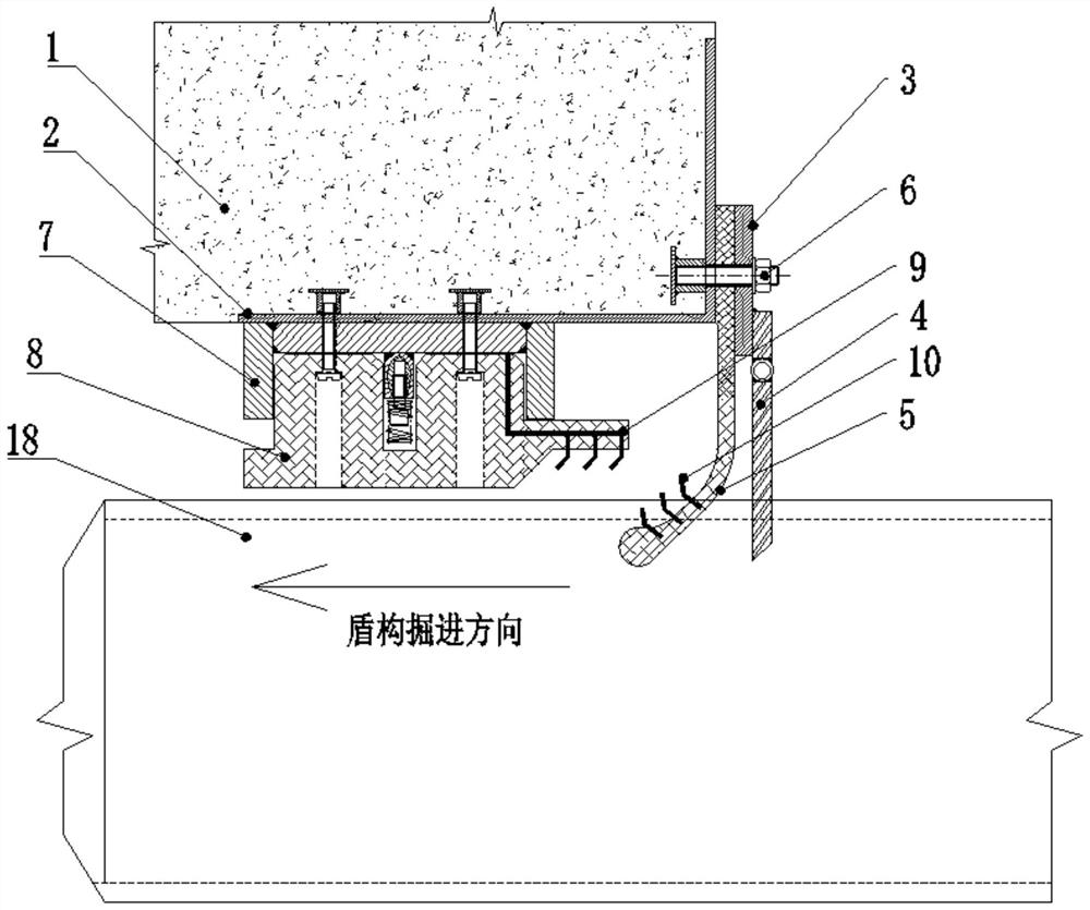
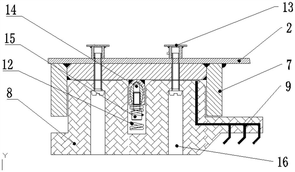
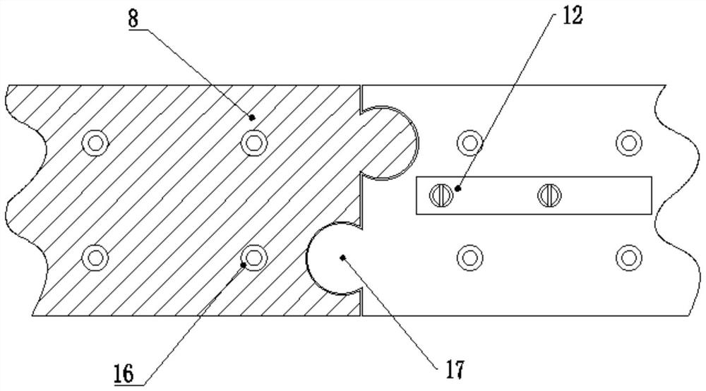
The invention belongs to the technical field of shield tunnel construction, and in particular relates to a new type of pressure-regulating self-sealing structure for a starting and receiving tunnel door of a shield tunnel. The problem of incomplete sealing of the sealing structure in the prior art and easy leakage of water and slurry when the pressure of water and slurry is high is solved. The technical scheme of the present invention is: including a pre-embedded ring plate and a fixed ring plate, the cross-sectional shape of the pre-embedded ring plate is L-shape, one side is perpendicular to the axis of the shield machine, and the other side is with the shell of the shield machine In parallel, the side of the embedded ring plate that is perpendicular to the axis of the shield machine is provided with a steel-edged rubber cord, and the steel-edged rubber cord is located between the embedded ring plate and the fixed ring plate and fixed by tightening bolts. The fixed ring plate is connected with a folding flap, and the inner side of the embedded ring plate is provided with a compression type self-sealing structure. The invention adopts a double-layer self-sealing structure and an intermediate resistance type compression spring seal, which can effectively solve the problem of difficulty in sealing the rubber curtains of the tunnel door, and is suitable for the sealing of the shield starting and receiving tunnel doors.

Description

technical field [0001] The invention belongs to the technical field of shield tunnel construction, and in particular relates to a new type of pressure-regulating self-sealing structure for a starting and receiving tunnel door of a shield tunnel. Background technique [0002] With the rapid development of modern society and the large-scale promotion of urbanization, the traffic pressure in central cities is increasing, and people's demand for urban subways is increasing. Shield tunnel construction is widely used because of its advantages of high degree of mechanization, fast construction speed, and little impact on ground buildings. In shield construction, shield initiation and reception is one of the most important steps. In the initial stage, safety accidents such as water gushing, sand gushing, and permeable subsidence may occur at the gate of the cave. Especially in the condition of rich water and soft soil, the ground subsidence, collapse and even the collapse of buildin...

Claims


Application Information

Patent Timeline
Patent Type & Authority Patents(China)
IPC IPC(8): E21D9/06E21D9/14E21D11/38
CPCE21D9/0635E21D9/14E21D11/38E21D11/383
Inventor 董晓珂章龙管李开富武焱林李云黄斌
Owner CHINA RAILWEY ENG SERVICE CO LTD
Learn More