Directional flow valve with continuous flow adjustment function and control method thereof

A flow valve and flow technology, applied in the direction of earthwork drilling, fluid pressure actuation device, fluid pressure actuation system components, etc., can solve the problems of precise control of flow, damage to pipelines, sealing, explosion of cylinders, etc., and achieve continuous change of flow , Reduce the effect of hydraulic shock

Active Publication Date: 2022-02-11
TAIYUAN UNIV OF TECH
View PDF0 Cites 0 Cited by
  • Summary
  • Abstract
  • Description
  • Claims
  • Application Information

AI Technical Summary

Problems solved by technology

However, at present, the hydraulic system of the hydraulic support all uses 200-400 liters / min high-flow electro-hydraulic switch valve or manual control valve to adjust the posture of the hydraulic support. Since the electro-hydraulic switch valve or manual control valve cannot accurately control the flow, the hydraulic support Inaccurate posture adjustment affects the state of roof support and poses a great safety hazard in the production process
On the other hand, especially the process of opening or closing the large-flow electro-hydraulic switching valve is completed instantaneously. The valve port suddenly opens to the maximum value or closes suddenly, and the flow rate is sudden, causing a strong hydraulic shock to the hydraulic system. The shock wave will Destruction of structural parts such as pipelines and seals, or even cylinder explosion, will also cause great safety hazards underground and affect production efficiency

Method used


Image

  • Directional flow valve with continuous flow adjustment function and control method thereof
  • Directional flow valve with continuous flow adjustment function and control method thereof
  • Directional flow valve with continuous flow adjustment function and control method thereof

Examples


Embodiment Construction

[0023] Below in conjunction with accompanying drawing, the present invention is described in further detail.

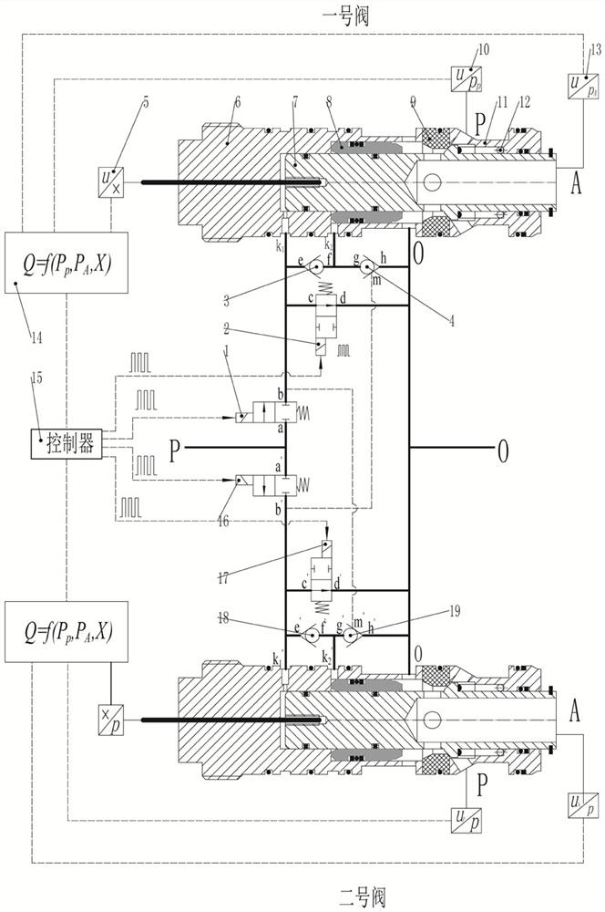
[0024] A main valve, including a liquid return valve sleeve 6, a liquid inlet valve core 7, a liquid return valve core 8, a valve seat 9, a liquid inlet valve sleeve 11 and a return spring 12, and the liquid inlet valve core 7 is inserted into the liquid return valve sleeve 6, the left end face of the liquid inlet valve core 7 and the end face of the liquid return valve sleeve 6 form a liquid inlet valve core control chamber, and the liquid inlet valve core control chamber is connected with the liquid inlet and outlet k on the liquid return valve sleeve 6 1 The liquid return valve sleeve 6 is provided with a step inside, and the left end surface of the liquid return valve core 8 forms a liquid return valve core control cavity with the step surface, and the liquid return valve core control cavity is connected with the liquid return valve sleeve 6. Liquid inlet and outl...


PUM


Abstract

The invention relates to a directional flow valve for a hydraulic support, in particular to a directional flow valve with the function of continuously adjusting flow and a control method thereof. Including main valve, pilot circuit and control part. The main valve includes the liquid return valve sleeve, the liquid inlet valve core, the liquid return valve core, the valve seat, the liquid inlet valve sleeve, and the return spring. The pilot circuit includes a normally closed high-speed switch valve, a normally open high-speed switch valve, a one-way valve, A one-way valve, the control part includes a pressure sensor, a displacement sensor, a flow calculation unit and a controller. The invention can not only realize the continuous adjustment of the direction and flow of the hydraulic support, precisely control the flow, improve the attitude control accuracy of the hydraulic support, but also realize the soft start of the main valve spool and reduce the hydraulic impact caused by the sudden opening and closing of the spool.

Description

technical field [0001] The invention belongs to the technical field of pure water or high water-based directional flow control valves, in particular to a directional flow valve with continuous flow adjustment function and a control method thereof. Background technique [0002] The coal mine underground hydraulic support supports and manages the roof by adjusting its posture, providing a safe working space for underground personnel and equipment. However, at present, the hydraulic system of the hydraulic support all uses 200-400 liters / min high-flow electro-hydraulic switch valve or manual control valve to adjust the posture of the hydraulic support. Since the electro-hydraulic switch valve or manual control valve cannot accurately control the flow, the hydraulic support Inaccurate attitude adjustment affects the state of roof support and poses a great safety hazard in the production process. On the other hand, especially the process of opening or closing the large-flow elec...

Claims


Application Information

Patent Timeline
Patent Type & Authority Patents(China)
IPC IPC(8): E21D23/26F15B13/02F15B21/02
CPCE21D23/26F15B13/02F15B21/02
Inventor 廖瑶瑶张越廉自生赵瑞豪张恒李润泽
Owner TAIYUAN UNIV OF TECH
Why Eureka
Try Eureka