
Fan braking circuit

A technology of fans and circuits, applied in pump control, non-variable-capacity pumps, machines/engines, etc., can solve problems such as inability to effectively brake quickly and stop, loss of braking function, and fan design space limitations.

Pending Publication Date: 2020-11-10
ASIA VITAL COMPONENTS SHENZHEN CO LTD
View PDF0 Cites 0 Cited by
  • Summary
  • Abstract
  • Description
  • Claims
  • Application Information

AI Technical Summary

Problems solved by technology

[0003] The main requirement of the power-off braking function of the fan is to quickly stop the fan blades completely, so as to avoid safety problems caused by the operator accidentally touching the fan blades. The side that is consumed is difficult to effectively meet the needs of fast (or emergency stop) braking when the fan is powered off
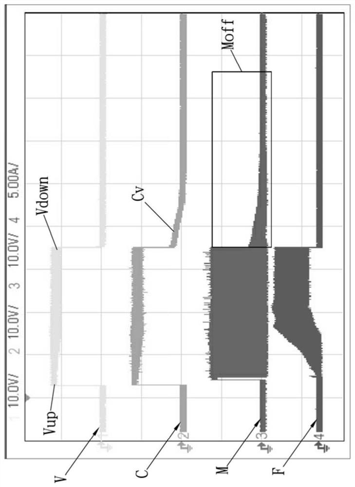
exist Figure 1B , is the actual measurement waveform diagram of the existing input power Vin, capacitor 11 voltage, motor coil 122 voltage and fan current. In the figure, the waveform symbol of the input power Vin is V, and the arrow Vup in the waveform V of the input power Vin represents Power on the input power Vin (i.e. the fan is powered on) and the arrow Vdown represents the power off of the input power Vin (i.e. the fan is powered off), the symbol of the voltage waveform of the capacitor 11 is C, and the arrow Cv in the voltage waveform C of the capacitor 11 represents After the fan is powered off, the capacitor 11 releases the stored voltage and is quickly consumed by the motor coil 122 and is lower than the conduction voltage of the upper arm MOS transistor switch 121, so it cannot effectively brake and stop quickly; the waveform symbol of the motor coil voltage is M, and the motor The dotted frame area Moff in the coil voltage waveform M shows a sloping downward line, which means that the fan motor is still running (that is, the fan blade is still rotating) and there is continuous back EMF voltage generation; the symbol of the fan current waveform is F, so according to the above The actual measured waveform results show that the existing capacitor 11 can only cause the fan motor 12 to brake for a short time and then lose the braking function, so that the fan blade must wait until the fan blade itself rotates until the inertial force disappears before it can come to a complete standstill. In the process of self-rotation until the inertial force is eliminated, there will also be a problem of reaction potential
Therefore, at present, if the industry wants to improve this part, it is generally to enlarge the capacitance specification size of the capacitor 11 to increase the capacitance. However, the design space of the fan is often limited, so it is necessary to choose a larger size / size within the limited space specification. Capacitors 11 with larger capacitance values ​​may be used in parallel with multiple capacitors 11, but it is impossible to use larger and bulky capacitors 11 that allow the fan to stop quickly. Due to the above factors, the overall cost will increase and the Fan power-off brake circuit 1. The overall size of the fan cannot be miniaturized, and the benefit of improvement is not obvious

Method used


Image

  • Fan braking circuit
  • Fan braking circuit
  • Fan braking circuit

Examples


Embodiment Construction

[0025] The above-mentioned purpose of the present invention and its structural and functional characteristics will be described according to the preferred embodiments of the accompanying drawings.

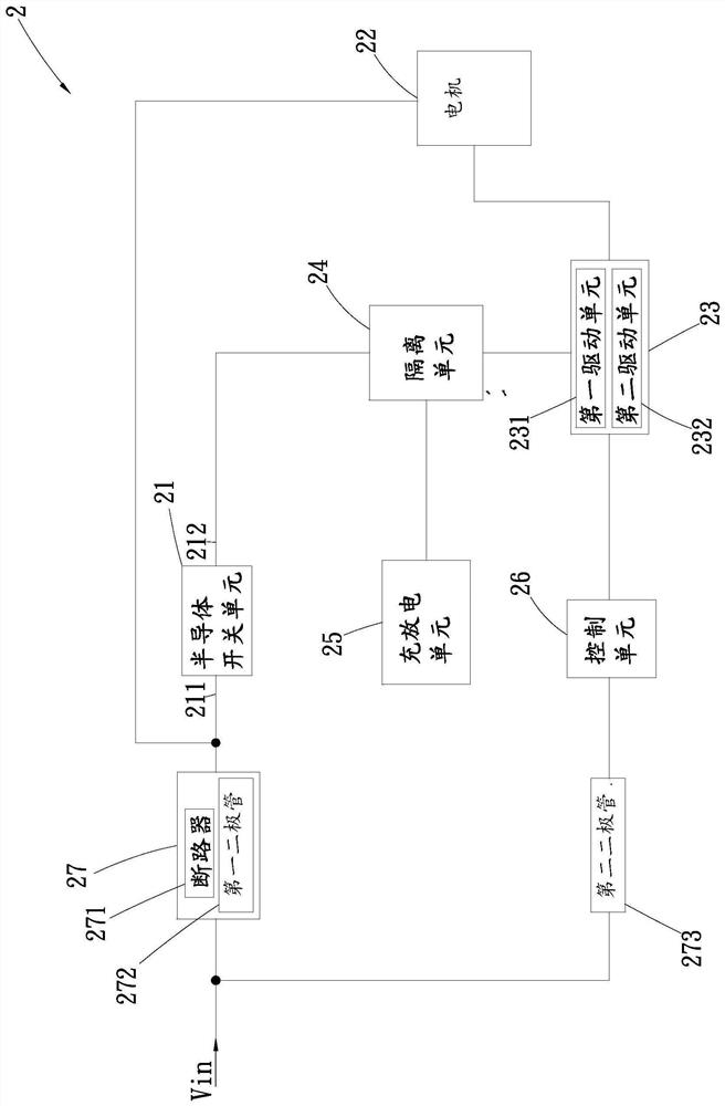
[0026] The present invention provides a fan braking circuit, please refer to Figure 2A It is a block diagram of a fan brake circuit according to an embodiment of the present invention; Figure 2B for the invention Figure 2A The circuit diagram of the fan brake circuit; Figure 2C It is a circuit diagram of a fan braking circuit in a feasible embodiment of the present invention; Figure 3A It is a block diagram of the fan brake circuit of an alternative embodiment of the present invention; Figure 3B for the invention Figure 3A The circuit diagram of the fan brake circuit; Figure 4 It is an actual measurement waveform diagram of the input power supply, the capacitor voltage of the charging and discharging unit, the motor coil voltage and the fan current according to an embo...


PUM


Abstract

The invention provides a fan braking circuit. The fan braking circuit comprises a semiconductor switch unit, a motor, a motor driving circuit, an isolation unit, a charging and discharging unit, and acontrol unit. The motor, the semiconductor switch unit, and one end of the control unit receive an input power supply. The motor driving circuit is in electric connection with the motor and the otherend of the control unit. The isolation unit is in electric connection with the other end of the semiconductor switch unit and the motor driving circuit and the charging and discharging unit. When a fan is powered off, the semiconductor switch unit is disconnected from the motor. The motor driving circuit receives an operation voltage provided by the charging and discharging unit and transmits a driving signal to the motor, so that the motor forms a short circuit loop to perform braking. Through the design of the fan braking circuit, the effects that the fan is quickly braked in case of powerfailure and the cost is reduced are effectively achieved.

Description

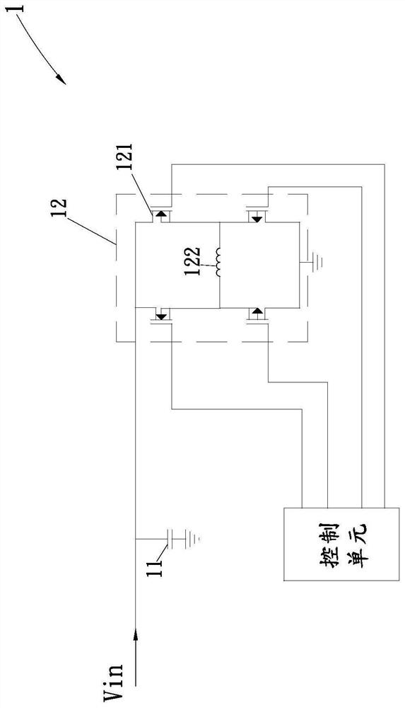
technical field [0001] The invention relates to a fan braking circuit, in particular to a fan braking circuit capable of quickly stopping the fan when power is off and reducing costs. Background technique [0002] see Figure 1A , the existing fan power-off braking circuit 1 is mainly electrically connected to an input power supply Vin through a capacitor 11 (usually an aluminum electrolytic capacitor), and the capacitor 11 is used to receive and store the input power supply Vin, and when the fan is powered off, the Capacitor 11 releases the stored voltage to directly switch on the upper bridge (upper arm) MOS transistor 121 in the motor 12, so that the motor coil 122 forms a short circuit, and then the phenomenon of fan motor braking is reflected. At the same time, the braking process will The counter electromotive force is generated and then recharged to the capacitor 11, so that the kinetic energy is converted into electric energy and then the braking function is generate...

Claims


Application Information

Patent Timeline
IPC IPC(8): F04D27/00
CPCF04D27/00F05D2260/90F05D2270/54
Inventor 黄柏胜
Owner ASIA VITAL COMPONENTS SHENZHEN CO LTD
Learn More