Motor controller with laminated busbar heat dissipation structure

A technology of motor controllers and laminated busbars, which is applied to the circuit layout on the support structure, stackable modules, electrical components, etc., can solve the temperature requirements of high-power motor controllers, laminated bus The heat dissipation problem cannot be solved, and the heat dissipation capacity of the copper radiator can be reduced, so as to achieve the effect of lowering the temperature, improving the heat dissipation effect, and the installation method is simple

Active Publication Date: 2020-11-10
DONGFENG MOTOR CORP HUBEI
View PDF6 Cites 2 Cited by
  • Summary
  • Abstract
  • Description
  • Claims
  • Application Information

AI Technical Summary

Problems solved by technology

But the problem that comes with it is that the overall package of the insulating film concentrates and wraps the heat source, which reduces the heat dissipation capacity of the copper bar itself, which will bring a higher temperature rise, and temperature is the key factor affecting the performance of the insulating film. , the traditional way of relying on laminated busbars for natural heat dissipation can no longer meet the temperature requirements of high-power motor controllers
[0004] The Chinese utility model patent with the patent number CN201720273382.4 discloses an IGBT cooler for motor controllers. The motor controller housing is provided with a cooling water channel for heat dissipation, but only for IGBT module heat dissipation, laminated busbar heat dissipation problem still unresolved

Method used


Image

  • Motor controller with laminated busbar heat dissipation structure
  • Motor controller with laminated busbar heat dissipation structure
  • Motor controller with laminated busbar heat dissipation structure

Examples


Embodiment Construction

[0037] The following specific examples illustrate the present invention in further detail.

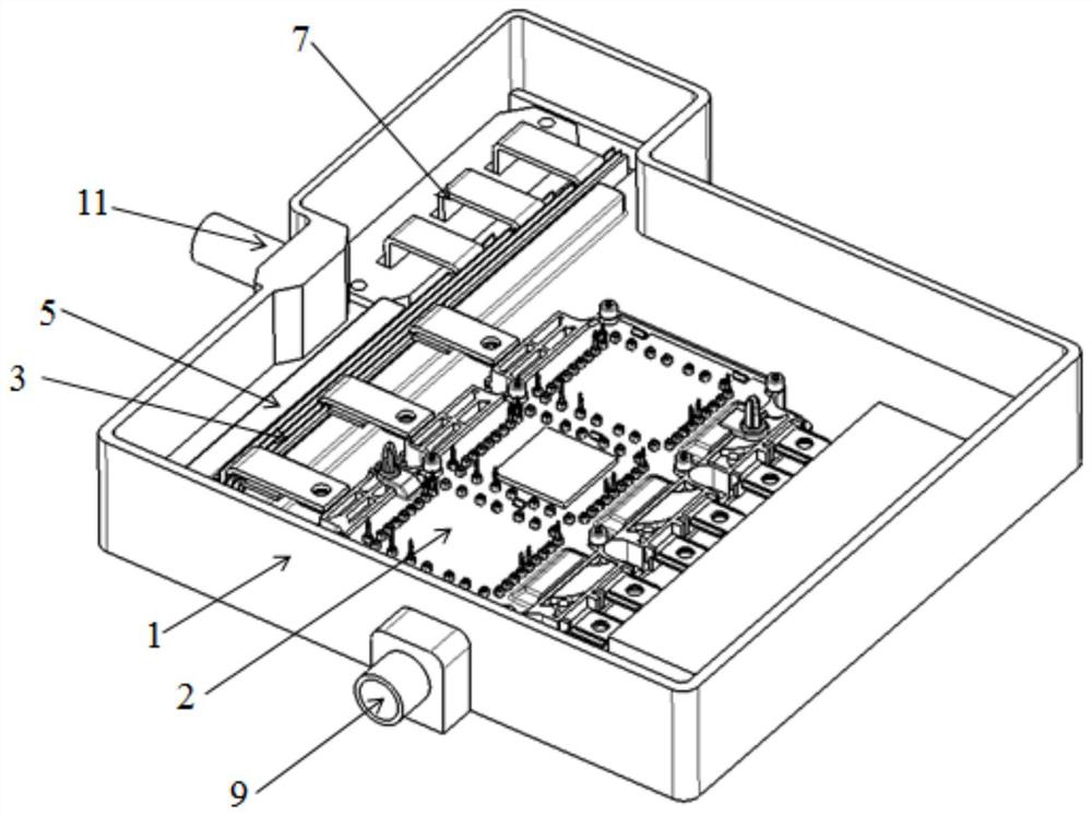
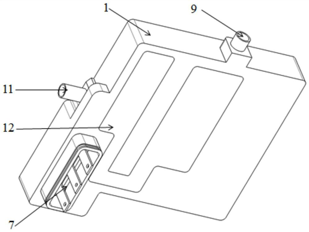
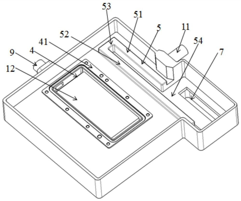
[0038] Such as Figure 1-10 As shown, a motor controller with a laminated busbar heat dissipation structure provided by the present invention includes a housing 1, an IGBT module 2 installed in the housing 1, and a laminated busbar 3. The housing 1 is provided with a top The opening cooling water tank 4, the IGBT module 2 is sealed and connected around the notch of the cooling water tank 4, and the casing 1 also protrudes to form a U-shaped installation part 5 with a horizontal projection, and an insulating heat conduction pad 6 is provided between the two arms of the installation part 5 And the laminated busbar 3 is arranged in the insulating heat conduction pad 6 for heat transfer, and the housing 1 is provided with an interface 7 corresponding to the output end of the laminated busbar 3 . The interior of the installation part 5 is provided with a cooling water channel 8 along the o...


PUM


Abstract

The invention discloses a motor controller with a laminated busbar heat dissipation structure, and the motor controller comprises a shell; an IGBT module and the laminated busbar, wherein the IGBT module and the laminated busbar are installed in the shell, the shell is provided with a cooling water tank with an opening in the top, the IGBT module is connected with the periphery of a tank opening of the cooling water tank in a sealed mode, and the shell further protrudes to form an installation part with the horizontal projection being in a U shape; an insulating heat conduction pad is arrangedbetween two arms of the mounting part; the laminated busbar is arranged in the insulating heat conduction pad for heat transfer in an attached manner; an interface is formed in the position, corresponding to the output end of the laminated busbar, of the shell; a cooling water channel is arranged in the mounting part along the outline, a water inlet leading to the cooling water tank is formed inthe shell, a connecting water channel leading to the end close to the cooling water channel is arranged at the position opposite to the water inlet pipe on the cooling water tank, and a water outlet is formed in the other end of the cooling water channel. According to the invention, the IGBT cooling water tank and the laminated busbar cooling water channel are communicated to form a set of coolingwater path, the complete heat conduction is formed, and the cooling of the laminated busbar is achieved.

Description

technical field [0001] The invention relates to the field of motor controllers for automobiles, in particular to a motor controller with a laminated busbar cooling structure. Background technique [0002] At present, the market demand for high-performance new energy vehicles is gradually increasing, and the power requirements of electric drive systems are also getting higher and higher. The motor controller is a key device for power transmission and conversion in the electric drive system. The increase in power will bring greater heat load to the related devices inside the motor controller. As the main heating device, the copper bar will reach a higher temperature. The temperature level, which has a serious impact on the life of the copper bar itself, insulation, and on the efficiency and reliability of the motor controller. [0003] The copper bar is the main power transmission device inside the motor controller, and it is also the main heat source. The high resistance he...

Claims


Application Information

Patent Timeline
Patent Type & Authority Applications(China)
IPC IPC(8): H05K7/20H05K7/02
CPCH05K7/023H05K7/20272H05K7/2039
Inventor 霍达胡磊尤长坤翟黎明张越晗
Owner DONGFENG MOTOR CORP HUBEI
Why Eureka
Try Eureka