[0021] In order to describe in detail the technical content, structural features, achieved objectives and effects of the technical solution, the following detailed description will be given in conjunction with specific embodiments and accompanying drawings.
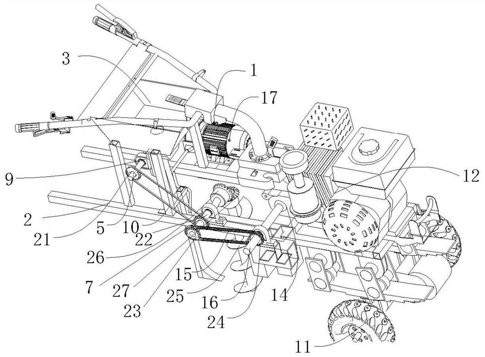
[0022] See figure 1 , A schematic diagram of a single screw pneumatic ditching fertilizer applicator figure 1 , Including frame 2, armrest 1, first rotating shaft 16, second rotating shaft 7, third rotating shaft 5, power unit, ditching device, air pump 17, walking device 11, trachea and fertilizing unit, frame 2 is on the right front to back A power device, a ditching mechanism, and a fertilizing device are sequentially fixedly arranged. The walking device is arranged under the frame. The walking device 11 includes a motor and a walking wheel. The motor is fixedly connected to the frame 2. Both the left and right ends of the motor are rotatably connected to one end of the rotating shaft. The other end of the rotating shaft passes through the frame 2 and is fixed to the walking wheel. connection.
[0023] The fertilizer application device includes a fertilizer box 3, an air pump 17, an outer tank wheel 19 fertilizer discharging device and a fertilizer pipe 6, and the fertilizer box 3 is fixedly connected to the frame 2 through a supporting plate 4. The outer groove wheel 19 fertilizer discharging device is fixedly arranged at the bottom of the fertilizer tank 3, the fertilizer pipe 6 is fixedly arranged at the bottom of the outer groove wheel 19 fertilizer discharging device, and the fertilizer tank 3, the outer groove wheel 19 fertilizer discharging device and the fertilizer pipe 6 are mutually connected. . The outer groove wheel 19 fertilizer discharging device includes an outer body of the fertilizer discharging device and a groove wheel 19, the fertilizer discharging device body 20 is fixedly connected with the bottom surface of the fertilizer tank 3, and the groove wheel 19 is rotatably connected in the fertilizer discharging device body 20. The slot wheel 19 fertilizer discharging device can control the amount of organic fertilizer discharged during the fertilization process. The air pump 17 is fixedly installed on the frame 2. The air pump 17 is connected to the fertilizer pipe 6 through the air blowing pipe I18. After the air pump 17 is energized, the fan rotates to form an air flow and blows air into the fertilizer pipe 6 through the air blowing pipe I. To prevent the fertilizer from clogging in the fertilizer pipe 6. The blowing pipe II28 is located above the opener. One end of the blowing pipe II28 is connected with the output end of the air pump, and the other end is in front of the upper end of the fertilizer pipe 6, and the blowing pipe II28 can blow downward.
[0024] The power plant includes an engine device 12 and a gearbox 14, a first rotating shaft 16, a second rotating shaft 7, a third rotating shaft 5, a third driving wheel 22, a third driven wheel 21, a first driving wheel 24, and a first driven wheel 23, The engine device 12 and the gearbox 14 are both fixedly arranged on the frame 2, and the gearbox 14 is located under the engine device 12, and the two are in transmission connection. An armrest 1 is installed on the gearbox 14, and the armrest 1 is located behind the engine device 12. The armrest 1 can control the start and stop of the engine device 12 and control the direction of the machine.
[0025] The ditching device includes an auger 25 and a ditch opener. The output end of the gearbox 14 is rotatably connected with one end of the first rotating shaft 16, the first rotating shaft 16 is arranged perpendicular to the gearbox 14 and the frame 2 is rotatably connected. The other end of the first rotating shaft 16 is fixedly provided with a first driving wheel 24, the first rotating shaft 16 is rotatably connected with the frame 2 through a fixed block 9, a bearing is nested on the fixed block 9, and the first rotating shaft 16 rotates with the fixed block 9 through the bearing connection. The second rotating shaft 7 is arranged parallel to the first rotating shaft 16 and is rotatably connected with the frame 2 through a fixed block 9. One end of the second rotating shaft 7 is fixedly connected with a bevel gear I26, and the bevel gear I26 is in transmission connection with the bevel gear I26. The bevel gear I26 meshes with each other, the bevel gear I26 is fixedly arranged at the upper end of the auger 25, the auger 25 is arranged perpendicular to the second rotating shaft 7, the auger 25 is located in front of the fertilizer pipe 6, and the auger 25 and the fertilizer pipe 6 are in the same straight line on.
[0026] The opener is located between the auger 25 and the fertilizer pipe 6, and the opener is arranged parallel to the auger 25. The upper end of the opener is fixedly connected to the frame 2, and the fertilizer pipe 6 is located behind the opener and is connected to the opener. Groove device connection. The fertilizer pipe 6 is fixedly arranged behind the opener. A first driven wheel 23 is fixedly arranged on the end of the second rotating shaft 7 away from the bevel gear I26. The first driven wheel 23 is sleeved on the end of the second rotating shaft 7 away from the bevel gear I, and is fixedly connected to the second rotating shaft 7. The first driving wheel 24 and the first driven wheel 23 are drivingly connected by the first transmission belt 15. The third driving wheel 22 is sleeved on the second rotating shaft 7 and located between the first driven wheel 23 and the fixed block 9. The third driving wheel 22 is fixedly connected to the second rotating shaft 7, and the third driven wheel 21 is sleeved The third transmission belt 10 is connected to the third driven wheel 21, the third driven wheel 21 is fixedly sleeved at one end of the third rotating shaft 5, and the other end of the third rotating shaft 5 is connected to the outer sheave 19 for the fertilizer discharging device. The three rotating shafts 5 and the frame 2 are rotatably connected by a fixed block 9. The first rotating shaft 16 is in transmission connection with the second rotating shaft 7 through the first driving wheel 24 and the first transmission belt 15, that is, driving the second rotating shaft 7 to rotate. The second rotating shaft 7 rotates to drive the bevel gear I26 to rotate, which in turn drives the bevel gear II27 to rotate. The rotation of the gear I26 drives the auger 25 to rotate, and the auger 25 starts to work. The rotation of the second rotating shaft 7 can drive the third driving wheel 22 and the third transmission belt 10 to drive the third rotating shaft 5 to rotate. The rotation of the third rotating shaft 5 can drive the outer groove wheel 19 to operate the fertilizer discharging device. The rotation rate of the third rotating shaft 5 can be controlled. The amount of fertilizer discharged by the groove wheel 19 fertilizer discharging device during the fertilization process.
[0027] See figure 2 Shown is a schematic diagram of a single screw pneumatic ditching fertilizer applicator figure 2 The opener is located between the auger 25 and the fertilizer pipe 6, and the opener is arranged parallel to the auger 25. The upper end of the opener is fixedly connected to the frame 2, and the fertilizer pipe 6 is located behind the opener and is connected to the The opener is fixedly connected. One end of the air pipe blowing II is connected with the air pump, and the other end is located at the upper end of the opener, and the air outlet is downward. The blower II28 can continuously blow from top to bottom on the opener, so it can prevent soil from sticking to the opener and prevent weeds from entanglement. The fertilizer pipe 6 is arranged behind the opener, which can block the soil and gravel lifted up by the auger 25 when the auger 25 is working, to prevent damage to the fertilizer pipe 6 to a certain extent.
[0028] See image 3 with Figure 4 Shown are a schematic diagram of a fertilizing device of a single-screw pneumatic ditching fertilizer applicator and a schematic diagram of a fertilizing device of a single-screw pneumatic ditching fertilizer applicator without an air pump. The fertilization device includes an air pump 17, a fertilizer box 3, an outer tank wheel fertilizer discharging device and a fertilizer pipe 6. The fertilizer tank 3 is fixedly connected to the frame 2 through a supporting plate 4, and the outer tank wheel fertilizer discharging device is fixedly arranged at the bottom of the fertilizer tank. The grooved wheel fertilizer discharging device includes a fertilizer discharging body 20, a third rotating shaft 5, and a grooved wheel 19. The fertilizer discharging body 20 is fixedly connected to the bottom surface of the fertilizer tank 3, and the grooved wheel 19 is rotatably connected in the fertilizer discharging body 20 , And the sheave wheel 19 is located under the fertilizer mouth of the fertilizer tank 3. One end of the sheave wheel 19 is fixedly connected to one end of the third rotating shaft 5, and the other end of the third rotating shaft 5 is drivingly connected to the third rotating unit, and the third rotating shaft 5 Rotate and connect with frame 2. The third rotating shaft 5 can control the rotation rate of the sheave 19, thereby controlling the amount of fertilizer discharged.
[0029] When the present invention is in use, the power output end of the engine device 12 is connected to the power input end of the gearbox 14, that is, the engine device 12 provides power to drive the gearbox 14 to run, and the gearbox 14 drives the first shaft 16 to rotate. 16 is drivingly connected to the second rotating shaft 7 through the first driving wheel 24 and the first transmission belt 15, so when the first rotating shaft 16 rotates, the second rotating shaft 7 can be driven to rotate. The rotation of the second rotating shaft 7 drives the bevel gear I26 to rotate, which in turn drives the bevel gear I26 to rotate, and the rotation of the bevel gear II27 drives the auger 25 to rotate. While the walking device 11 is running forward, the auger 25 rotates to ditch the field. When working, the auger 25 can go around a point at the ditch and pass through the spiral blade to ditch the center. A furrow opener is provided to prevent the soil lifted up by the auger 25 from covering the fields. While the furrow opener opens the furrow, fertilizer can fall into the opened furrow from the fertilizer pipe 6 located behind the furrow opener. . When the Chulong 25 ditched, the pressure of the land is greater, and the hard ground or fields with more rocks can be reclaimed first to make the soil soft and convenient for the opener behind to open the ditch. It can be used for trenching in hard and wasteland. The rotation of the second rotation shaft 7 can drive the third driving wheel 22 and the third transmission belt 10 to drive the third rotation shaft 5 to rotate. The rotation of the third rotation shaft 5 can drive the sheave 19 to rotate. The third rotation shaft 5 can further control the rotation rate of the sheave 19, In turn, the amount of fertilizer discharged by the outer groove wheel fertilizer discharge device in the fertilization process is controlled. When the air pump 17 is energized, the fan rotates to form an air flow and blows air into the fertilizer pipe 6 through the air blowing pipe I18, which can prevent the fertilizer from being blocked in the fertilizer pipe 6. The blowing pipe I18 is fixedly connected to the blowing pipe II28. The blowing pipe II28 is located above the opener. The blowing pipe II28 can be blown down from the upper end of the opener through the air pump 17, which can prevent the opener from sticking to the opener. , And can prevent weeds from entanglement. The whole machine of the invention has simple design structure, small size, low power consumption, convenient operation, strong practicability and adaptability, and is suitable for working in mountainous environments such as tea gardens.
[0030] It should be noted that in this article, relational terms such as first and second are only used to distinguish one entity or operation from another entity or operation, and do not necessarily require or imply one of these entities or operations. There is any such actual relationship or order between. Moreover, the terms "include", "include" or any other variants thereof are intended to cover non-exclusive inclusion, so that a process, method, article, or terminal device that includes a series of elements includes not only those elements, but also those that are not explicitly listed. Other elements listed, or also include elements inherent to this process, method, article or terminal device. Without more restrictions, the elements defined by the sentence "including..." or "including..." do not exclude the existence of other elements in the process, method, article, or terminal device that includes the elements. In addition, in this article, "greater than", "less than", "exceeds", etc. are understood as not including the number; "above", "below", "within", etc. are understood as including the number.
[0031] Although the foregoing embodiments have been described, those skilled in the art can make additional changes and modifications to these embodiments once they learn the basic creative concept, so the foregoing is only the implementation of the present invention For example, this does not limit the scope of patent protection of the present invention. Any equivalent structure or equivalent process transformation made by using the content of the description and drawings of the present invention, or directly or indirectly applied to other related technical fields, are included in the same principle. The invention is within the scope of patent protection.