
A Pulse Power Supply for Kicking Rail Magnets

A technology of pulse power supply and magnet, which is applied in the field of pulse power supply of rail kick magnets, to achieve the effects of reducing current stabilization time, strong withstand voltage and reducing ripple

Active Publication Date: 2021-06-11
HUAZHONG UNIV OF SCI & TECH
View PDF0 Cites 0 Cited by
  • Summary
  • Abstract
  • Description
  • Claims
  • Application Information

AI Technical Summary

Problems solved by technology

The existing rail kick magnet power supply scheme can realize trapezoidal or sine-like output with a repetition rate up to gigahertz, but it is difficult to simultaneously output a trapezoidal wave with a repetition rate of thousands of hertz, and can work in DC model

Method used


Image

  • A Pulse Power Supply for Kicking Rail Magnets
  • A Pulse Power Supply for Kicking Rail Magnets
  • A Pulse Power Supply for Kicking Rail Magnets

Examples


Embodiment Construction

[0030] In order to make the object, technical solution and advantages of the present invention clearer, the present invention will be further described in detail below in conjunction with the accompanying drawings and embodiments. It should be understood that the specific embodiments described here are only used to explain the present invention, not to limit the present invention. In addition, the technical features involved in the various embodiments of the present invention described below can be combined with each other as long as they do not constitute a conflict with each other.

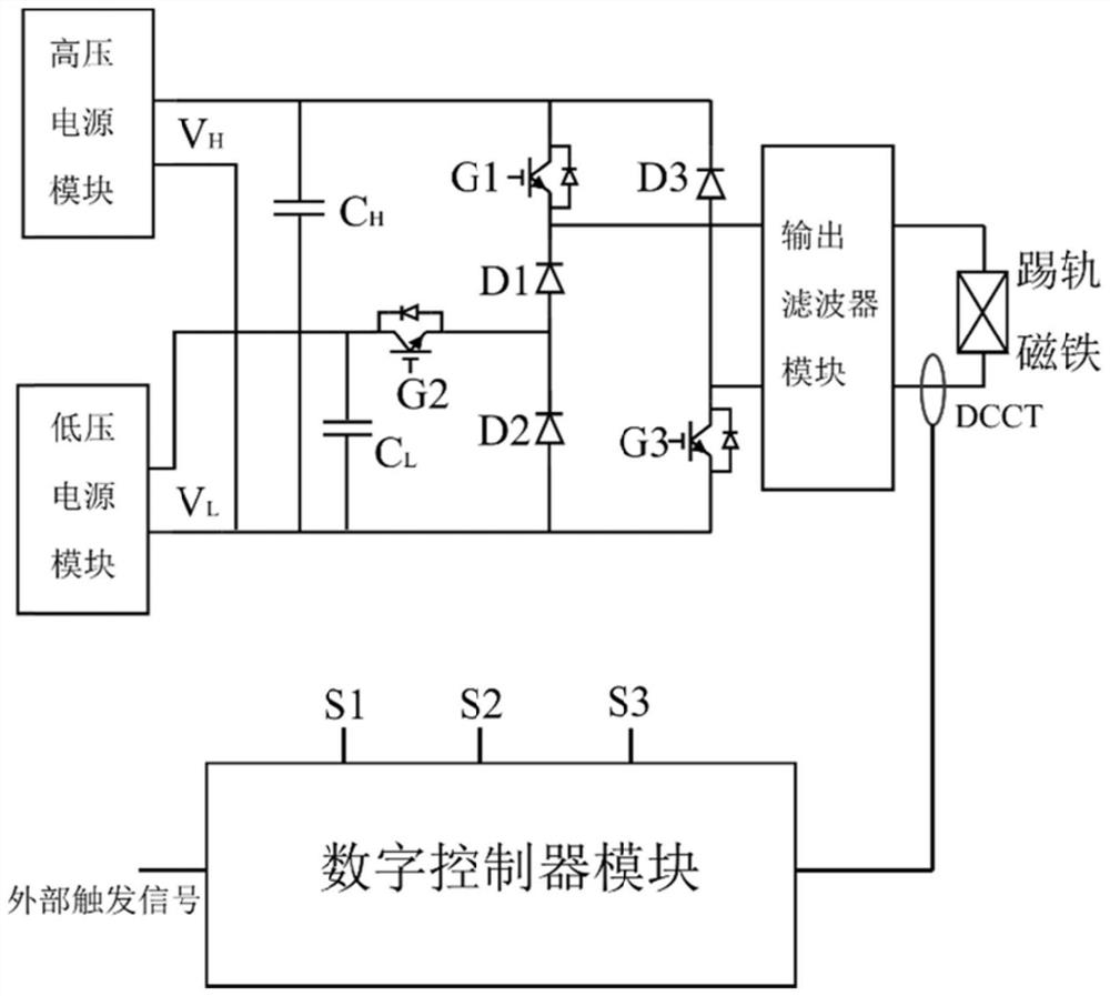
[0031] Such as figure 1 Shown is the principle diagram of the pulse power supply of the kick rail magnet provided by the present invention. Among them, the kick rail magnet is used for the fast switching of the power point switching process and the energy switching process of the proton therapy device; it can work in DC mode and provide a safety interlock for the treatment device in an emergenc...


PUM


Abstract

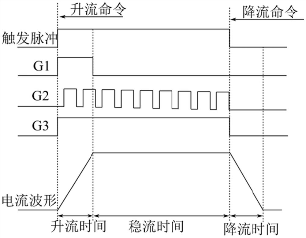
The invention discloses a pulse power supply for kick rail magnets, comprising: a high-voltage power supply module, a low-voltage power supply module, a power conversion unit and a digital controller module; Orderly flow between the magnet and the energy storage capacitor; one end of the digital controller module receives the external trigger control signal, one end is connected to the power conversion unit, and the other end samples the output current signal; the output current waveform of the pulse power supply is controlled by the external trigger signal , the rising edge of the trigger signal is the command to increase the current, and the falling edge of the trigger signal is the command to decrease the current. The switching device in the power conversion unit is driven by the digital controller module to achieve high-voltage rapid current-up, low-voltage steady current, and reduced output. current ripple. In this way, the output current waveform of the power supply of the present invention can be a trapezoidal wave, the repetition frequency can reach thousands of hertz, and the power supply can work in a direct current mode.

Description

technical field [0001] The invention belongs to the field of pulse power supply in proton heavy ion therapy, and more specifically relates to a pulse power supply of a rail kicking magnet. Background technique [0002] In cyclotron-based proton therapy devices, point scanning technology is usually used as the treatment terminal scanning method. The 250MeV continuous beam proton beam drawn from the cyclotron passes through the energy selection section to change the fixed energy proton beam into a 70MeV-240MeV continuous energy adjustable proton beam, and then enters the treatment room through the corresponding beam transport line. During treatment with pencil spot scanning, the proton beam needs to penetrate the patient for a few milliseconds before switching to the next spot. In the process of point-to-point switching and energy switching, a fast beam switch is needed to reduce unnecessary radiation dose, and it needs to be able to work in DC mode to provide a fast safety c...

Claims


Application Information

Patent Timeline
Patent Type & Authority Patents(China)
IPC IPC(8): H02M7/217A61N5/10H02M1/088H02M1/14
CPCA61N5/1065A61N2005/1087A61N2005/1092H02M1/088H02M1/14H02M7/217H02M1/0012
Inventor 秦斌韩文杰刘旭刘开锋陈曲珊李冬
Owner HUAZHONG UNIV OF SCI & TECH
Learn More