Lakebed pollutant continuous treatment device

A treatment device and pollutant technology, applied in the field of pollutant treatment, can solve the problems affecting the toughness of the blade, continuous treatment of unfavorable pollutants, clogging and other problems, and achieve the effect of rapid cutting and crushing

Inactive Publication Date: 2020-11-13
泉州市良创信息科技有限公司
View PDF10 Cites 0 Cited by
  • Summary
  • Abstract
  • Description
  • Claims
  • Application Information

AI Technical Summary

Problems solved by technology

[0003] After the lake bottom pollutants are salvaged, they need to be continuously treated, usually placed in a reactor for treatment. During the treatment process, due to the large amount of pollutants, the pollutants need to be continuously transported, usually through a screw conveyor. Pollutant transportation, the existing screw conveyor is prone to blockage during the conveying process. By using the crushing shaft to crush the pollutants, the garbage bags of the pollutants are easy to wrap around the crushing shaft, which affects the toughness of the blade, which is not conducive to Continuous treatment of pollutants

Method used


Image

  • Lakebed pollutant continuous treatment device
  • Lakebed pollutant continuous treatment device
  • Lakebed pollutant continuous treatment device

Examples


Embodiment 1

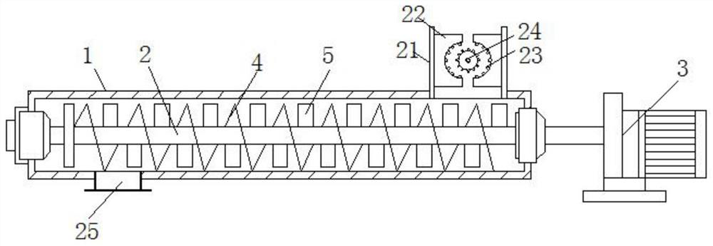
[0030] Such as Figure 1-4 As shown, the lake bottom pollutant continuous treatment device includes a shell 1,

[0031] A helical shaft 2 is provided for rotation in the housing 1, and one end of the helical shaft 2 extends out of the housing 1 and is provided with a servo motor 3;

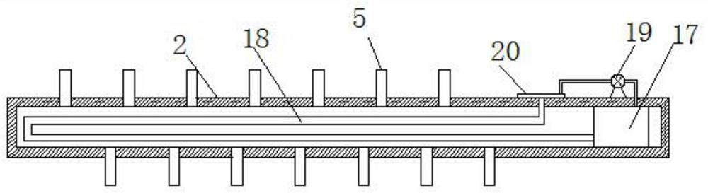
[0032] A plurality of helical blades 4 are evenly distributed along the horizontal axis on the helical shaft 2, and a crushing shaft 5 is arranged between every two helical blades 4, and the pulverizing shaft 5 is arranged on the helical shaft 2;

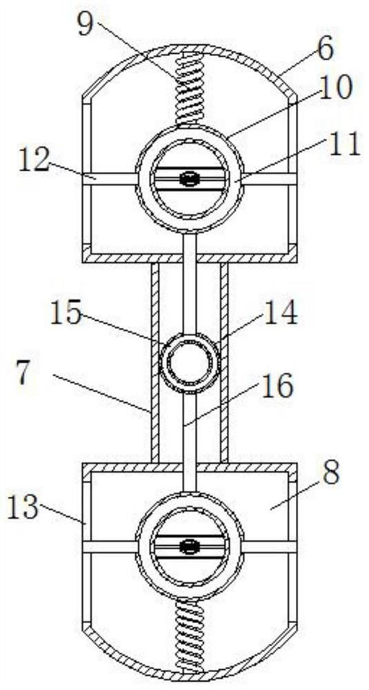
[0033] The crushing shaft 5 includes two crushing blades 6, connected by a connecting plate 7 between the two crushing blades 6, an installation cavity 8 is arranged in the crushing blade 6, an annular plate-10 is arranged in the installation cavity 8, and an annular plate-10 is arranged Elastic chamber 11 is arranged, and two blades 12 are symmetrically arranged on the elastic chamber 11 by sliding through the moving mechanism, and two strip-shaped sl...

Embodiment 2

[0038] Such as Figure 1-4 Shown, moving mechanism comprises strip plate 26, and strip plate 26 is arranged on ring plate one 10 centers, and in strip plate 26, symmetrical sliding is provided with moving rod 27, and one end of moving rod 27 stretches in ring plate one 10 and Connected with the elastic chamber one 11, the other end of the moving rod 27 is provided with a fixed plate 28, a first spring 29 is connected between the two fixed plates 28, and the top and bottom of the two fixed plates 28 are hinged with a diagonal bar 30 , the other ends of the two slanting bars 30 are jointly hinged with a horizontal plate 31, the blade 12 is fixedly mounted on the horizontal plate 31, and the blade 12 and the strip plate 26 slide longitudinally, when the elastic cavity 11 is heated and expanded, it drives The moving rod 27 moves, thereby driving the two fixed plates 28 to compress the first spring 29, thereby driving the hinged inclined rod 7 to move, thereby realizing the movemen...

Embodiment 3

[0040] Such as Figure 1-4 As shown, the lake bottom pollutant continuous treatment device includes a shell 1,

[0041] A helical shaft 2 is provided for rotation in the housing 1, and one end of the helical shaft 2 extends out of the housing 1 and is provided with a servo motor 3;

[0042] A plurality of helical blades 4 are evenly distributed along the horizontal axis on the helical shaft 2, and a crushing shaft 5 is arranged between every two helical blades 4, and the pulverizing shaft 5 is arranged on the helical shaft 2;

[0043] The crushing shaft 5 includes two crushing blades 6, connected by a connecting plate 7 between the two crushing blades 6, an installation cavity 8 is arranged in the crushing blade 6, an annular plate-10 is arranged in the installation cavity 8, and an annular plate-10 is arranged Elastic chamber one 11 is arranged, two blades 12 are symmetrically arranged on the elastic chamber one 11, and two strip-shaped slide holes 13 are symmetrically arran...


PUM


Abstract

The invention provides a lakebed pollutant continuous treatment device and relates to the field of pollutant treatment. The device comprises a shell. According to the device, a crushing shaft is composed of two crushing blades and a connecting plate, meanwhile first elastic cavities, a second elastic cavity and knives are arranged, the first elastic cavities and the second elastic cavity are driven by temperature rise to expand, and therefore the knives are driven to extend out of strip-like sliding holes to cut garbage bags wound around the crushing blades; at the same time, the second elastic cavity subjected to thermal expansion drives a connecting rod to move, so that a first mounting box is driven to move, and the garbage bags wound around the crushing blades are more convenient to cut and crush through sliding of the knives; and moreover, a condensing circulation device is arranged, so that the first elastic cavities and the second elastic cavity perform thermal expansion and cold contraction back and forth all the time, accordingly the knives extend back and forth in the strip-like sliding holes and perform back-and-forth cutting simultaneously, and therefore the garbage bags wound around the crushing blades can be quickly cut and crushed.

Description

technical field [0001] The invention relates to the field of pollutant treatment, in particular to a continuous treatment device for lake bottom pollutants. Background technique [0002] In recent years, due to a series of physical, chemical and biochemical processes such as municipal sewage, industrial wastewater, agricultural wastewater, surface runoff, and atmospheric dustfall, some or most of them have been deposited at the bottom of rivers and lakes, resulting in eutrophication of lakes and rivers. Lake bottom mud is not only an important reservoir of organic and heavy metal pollutants, but also a potential secondary pollution source of water bodies, and seriously endangers human health through the food chain. Reasonable disposal of bottom mud is one of the important ways to fundamentally solve water pollution. Sediment disposal needs to solve two problems, one is the remediation of organic matter-heavy metal polluted river and lake sediments, and the other is the dehyd...

Claims


Application Information

Patent Timeline
Patent Type & Authority Applications(China)
IPC IPC(8): B02C13/06B02C13/26B02C13/28B02C18/02B02C18/04
CPCB02C13/06B02C13/26B02C13/2804B02C18/0076B02C18/0092B02C18/02B02C18/04B02C2201/063
Inventor 戴景华何锋锋
Owner 泉州市良创信息科技有限公司
Why Eureka
Try Eureka