
Sheet metal forming method of multi-deep-cavity thin-wall part of aircraft

A technology of thin-walled parts and forming method, applied in the field of aircraft parts processing, can solve the problems of low processing efficiency, affecting the surface quality of parts, uneven material flow, etc. Effect

Active Publication Date: 2020-11-13
CHENGDU AIRCRAFT INDUSTRY GROUP
View PDF6 Cites 2 Cited by
  • Summary
  • Abstract
  • Description
  • Claims
  • Application Information

AI Technical Summary

Problems solved by technology

There are defects in this process. The material flow is uneven during the forming process, which may easily cause the bottom R of the deep cavity to be broken and the surrounding flanges to be severely wrinkled.
At the same time, the quality of parts depends heavily on the skill level of workers, and the state is unstable
The above factors lead to low processing efficiency, high cost, and poor quality of such parts, and the pass rate has been maintained below 30% for a long time, making it difficult to meet production needs.

Method used


Image

  • Sheet metal forming method of multi-deep-cavity thin-wall part of aircraft
  • Sheet metal forming method of multi-deep-cavity thin-wall part of aircraft
  • Sheet metal forming method of multi-deep-cavity thin-wall part of aircraft

Examples


Embodiment 1

[0033] The present embodiment provides a sheet metal forming method for multi-deep cavity aircraft thin-walled parts, comprising the following steps:

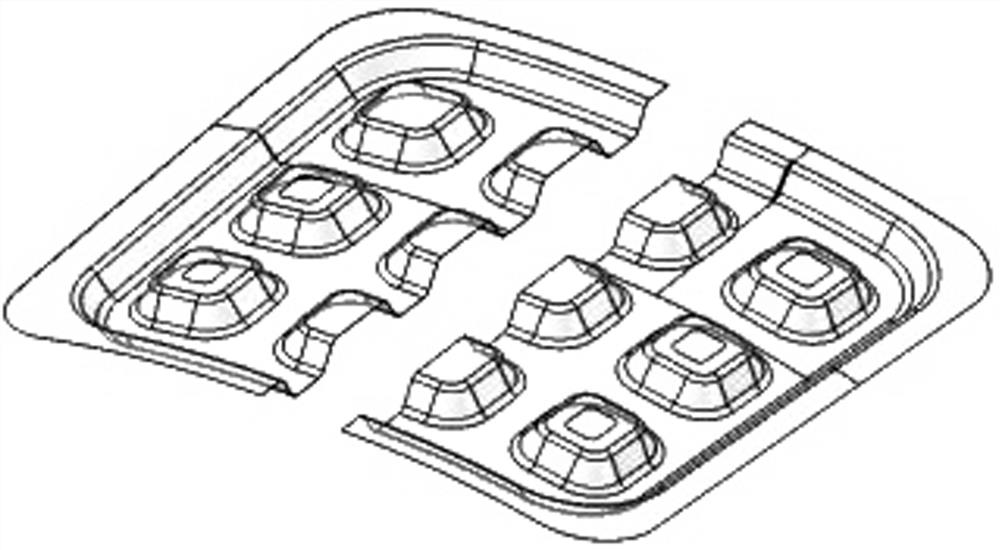
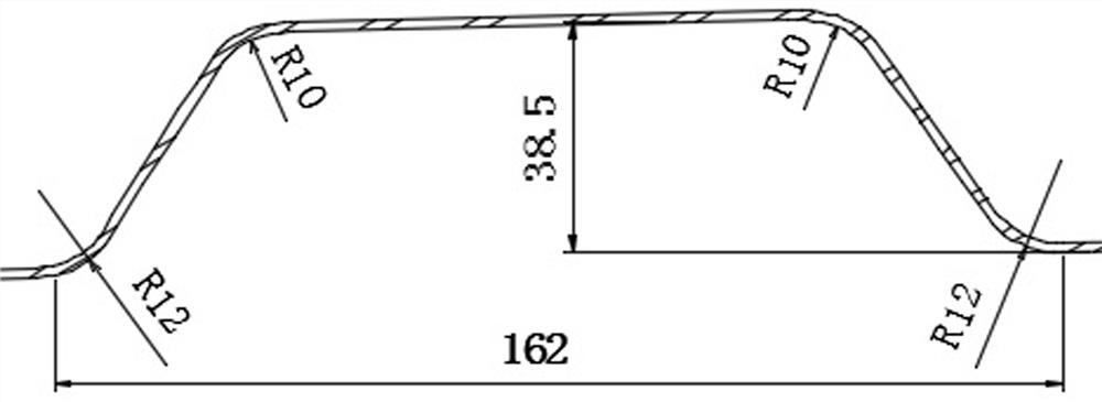
[0034] (1) Obtain the 3D digital model of the part according to the part forming process plan, so as to determine the type of deep cavity of the part and the size of the standard deep cavity; the 3D digital model of the part with deep cavity is as follows figure 1 Shown, standard deep cavity dimensions, such as figure 2 shown;

[0035] (2) According to the size of the deep cavity of the part, manufacture spherical deep drawing dies, deep drawing dies, and integral deep drawing dies;

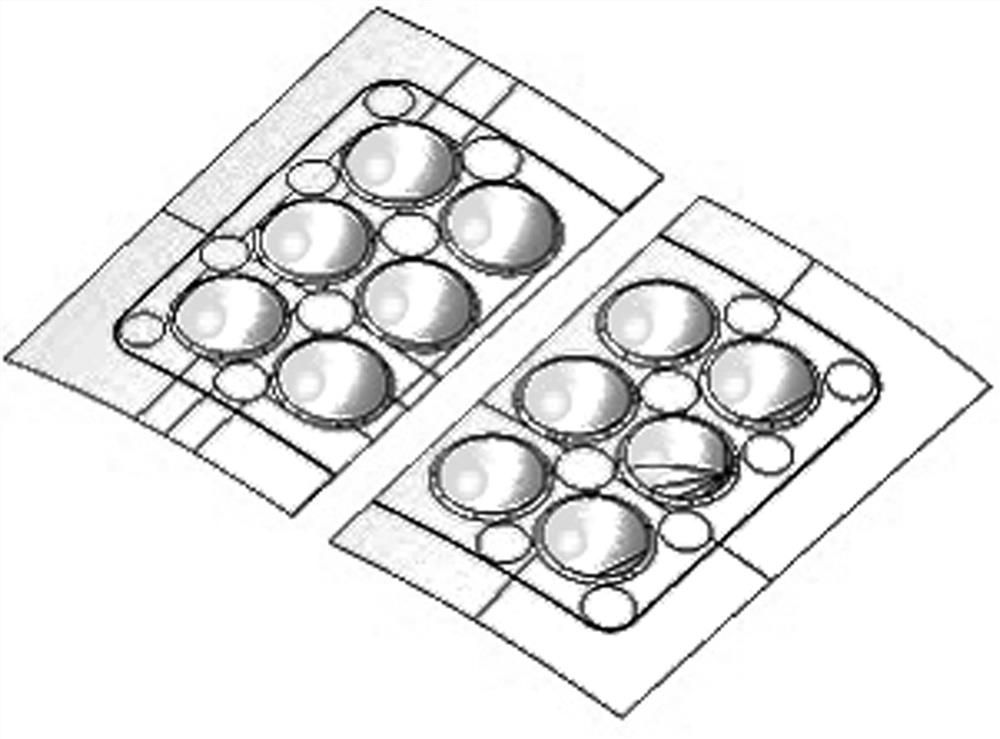
[0036] (3) Use a spherical deep drawing die to draw the part to be processed into a deep cavity into a hemispherical shape to form a part with a spherical deep cavity; the structure diagram of a part with a spherical deep cavity, such as image 3 As shown, the size diagram of the spherical deep cavity, such as Figure 4 shown;

[0037] (4) Us...

Embodiment 2

[0041] On the basis of the above-mentioned embodiments, this embodiment further defines the types of deep cavities of parts, such as Figure 6 , Figure 7 As shown, in the step (1), the types of the deep cavity of the part include fully enclosed deep cavity and semi-closed deep cavity. When the fully enclosed deep cavity is drawn, the mold needs to fully cover the deep cavity, and When drawing the semi-closed deep cavity, the opening does not need a mold to cover the deep cavity. For the semi-closed deep cavity, the opening part should be transitioned according to the slope to facilitate the flow of materials. Other parts of this embodiment are the same as those of the foregoing embodiment, and will not be repeated here.

Embodiment 3

[0043] This embodiment further defines the process of step (3) on the basis of the above embodiments. In the step (3), the ratio of the surface area of ​​the standard deep cavity to the spherical area of ​​the drawn hemispherical deep cavity is 1:1.02 ~1.08. Since other parts of this embodiment are the same as those of the foregoing embodiment, details are not repeated here.


PUM

PropertyMeasurementUnit
widthaaaaaaaaaa

Abstract

The invention discloses a sheet metal forming method of a multi-deep-cavity thin-wall part of an aircraft. The method is characterized by comprising steps as follows: 1) according to a part forming technical scheme, a three-dimensional digital model of the part is obtained, so that the type of deep cavities of the part and the size of a standard deep cavity are determined; 2) according to the sizeof the deep cavities of the part, a spherical surface drawing die, a deep drawing die and a shaping deep drawing die are manufactured respectively; 3) a to-be-machined part is drawn into a semi-spherical shape by the spherical surface drawing die, and a part with a spherical surface deep cavity is obtained; 4) the semi-spherical deep cavity is subjected to deep drawing by the deep drawing die continuously and enabled to reach depth of the standard deep cavity, and a part with a transition size deep cavity is obtained; and 5) the part with the transition size deep cavity is drawn by the shaping drawing die, a part with the standard deep cavity is formed finally, meanwhile, pressure maintaining is carried out, and degree of film sticking is ensured. According to the method, machining efficiency, qualification rate and forming quality can be increased, and high-quality, high-efficiency and low-cost deep cavity manufacture of the part is realized.

Description

technical field [0001] The invention relates to the technical field of aircraft parts processing, in particular to a sheet metal forming method for aircraft thin-walled parts with multiple deep cavities. Background technique [0002] Multi-deep cavity aircraft thin-walled parts are mainly bonded to the outer skin of the aircraft and used to support the outer skin of the aircraft, so their overall shape is curved. The overall bottom of the part is a large deep cavity with different directions. Multiple closed deep cavities and semi-closed deep cavities are distributed on the deep cavity, which is in a square structure. The bottom R is small, the structure is complex, the forming is difficult, and defects such as wrinkles and cracks are prone to occur. . The traditional processing technology is to adopt multi-pass drop forming, interspersed with manual wrinkle removal in the middle, and finally meet the technical requirements through manual correction. There are defects in t...

Claims


Application Information

Patent Timeline
Patent Type & Authority Applications(China)
IPC IPC(8): B21D22/26B21D22/30
CPCB21D22/26B21D22/30
Inventor 李晓军董锦亮门向南邓涛曾一畔成靖凌建兵李炎
Owner CHENGDU AIRCRAFT INDUSTRY GROUP
Learn More