
Manned air shaft inspection robot and air shaft inspection method

A technology for inspection robots and wind shafts, which is applied in the field of robots, can solve problems such as low battery power, skewed shafts, and deformation of the guiding device of the lifting system, and achieve the effect of improving efficiency and accuracy

Active Publication Date: 2020-11-13
CHINA UNIV OF MINING & TECH
View PDF7 Cites 3 Cited by
  • Summary
  • Abstract
  • Description
  • Claims
  • Application Information

AI Technical Summary

Problems solved by technology

During the long-term continuous operation of the wellbore, due to factors such as many strata crossings, complex geological conditions, and harsh operating environments, the wellbore has slight strains. These strains are extremely difficult to detect in a short period of time, and long-term accumulation may cause the wellbore to be skewed. Problems such as deformation of the guiding device of the lifting system, and even major vicious accidents such as wellbore fracture and water inrush caused by gradual accumulation to sudden change
Once the shaft of the wind shaft fails, the coal production will be paralyzed, seriously affecting the economic benefits of the coal mine and the safety of workers
Although the "Coal Mine Safety Regulations" stipulates the inspection frequency and requirements for coal mine shaft facilities, mine shaft disasters still occur from time to time
[0003] Aiming at the detection / monitoring of shaft faults in wind shafts, the applicant has obtained several research results after years of research, such as a wire rope twisting climbing robot mentioned in Chinese patent CN201910207682.6, which adopts the form of active climbing. Due to the weight limit, the carried battery power is small, even with a power generation device, it is difficult to withstand long-term work
Another example is the Chinese patent CN201510381205.3, which mentions a vertical rope climbing inspection robot for the steel wire rope tank of an ultra-deep shaft. problem, cannot be dealt with immediately
[0004] The robot involved in the above patent application has the problem of low battery life and cannot be repaired in real time
In addition, the existing robot inspection method is a one-time inspection method. The inspection of the structure such as the shaft and the tank road by the robot only relies on one inspection by the inspection agency, so it is difficult to guarantee the accuracy of the inspection results, and even Occurrence of missed detection

Method used


Image

  • Manned air shaft inspection robot and air shaft inspection method
  • Manned air shaft inspection robot and air shaft inspection method
  • Manned air shaft inspection robot and air shaft inspection method

Examples


Embodiment 1

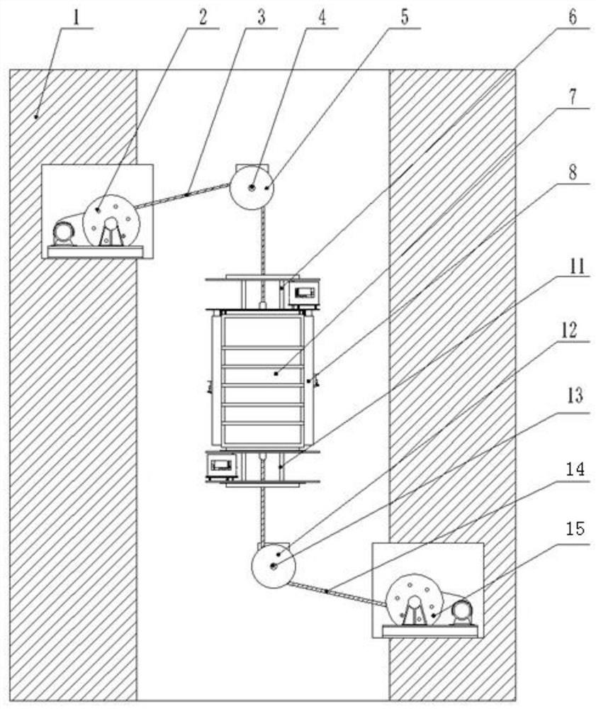
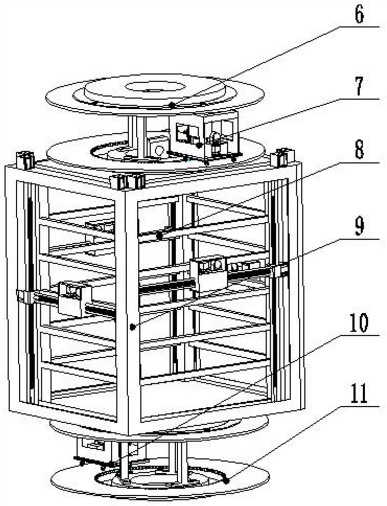
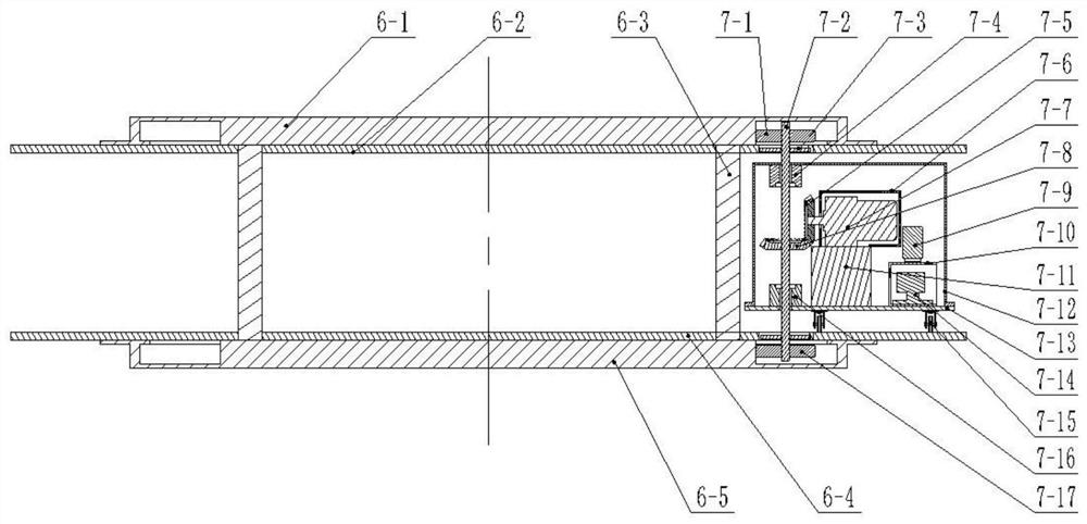
[0062] Such as Figures 1 to 4 As shown, the manned wind shaft inspection robot described in this embodiment includes a reel driving device, a manned device 8, a manned device inspection device 9, and a robot body, wherein:

[0063] The reel drive device described in this embodiment includes an upper reel drive device 2 and a lower reel drive device 15; the upper reel drive device 2 is arranged at the wellhead, and the lower reel drive device 15 is arranged at the bottom of the well;

[0064] The upper reel driving device 2 described in this embodiment includes an upper power device, an upper sky wheel 5, an upper sky wheel shaft 4 and an upper driving rope 3;

[0065] The power device described in this embodiment includes an industrial motor, a reducer, a reel, and an explosion-proof casing; the industrial motor is connected to the reel through the reducer, and an explosion-proof casing is installed outside the whole;

[0066] The lower reel driving device 15 described in th...

Embodiment 2

[0080] In order to solve the cost problem of the robot, this embodiment has made further improvements on the basis of Embodiment 1, and modified the arrangement position of the reel drive device, and the upper reel drive device 2 and the lower reel drive device 15 is arranged on the wellbore wall through the carrier frame.

[0081] The following will combine Figure 5 Detailed description The manned wind well inspection robot described in this embodiment includes a reel driving device, a manned device 8, a manned device inspection device 9, a robot body, an upper carrier 17, an upper carrier bracket 18, Lower carrier 20, lower carrier bracket 21, wherein:

[0082] The upper bearing frame 17 described in this embodiment is connected to the upper wellbore wall by pins, a carrier bracket is installed below the upper bearing frame 17, and an industrial motor and a reducer are installed on the wall bearing frame. The upper drum 16 is arranged in the middle of the shaft through th...


PUM


Abstract

The invention discloses a manned air shaft inspection robot and an air shaft inspection method. The inspection robot comprises a manned device and a manned device inspection device, wherein the manneddevice can lift in a shaft of an air shaft and comprises a rectangular wall surface, and the rectangular wall surface is defined by four side walls; the manned device inspection device is arranged onthe periphery of the rectangular wall surface of the manned device and can inspect the shaft wall of the shaft, a derrick and / or the rectangular wall surface of the manned device; the manned device inspection device is provided with inspection mechanisms a through a support aiming at each side wall of the manned device; the inspection mechanisms a can move in the planes where the inspection mechanisms a are located; and when the inspection mechanisms a detect faults, maintenance personnel carried on the manned device can perform real-time maintenance on areas where faults are located throughthe rectangular wall surface. Through the above arrangement, the conditions of the shaft wall of the shaft, the derrick and / or the manned device can be detected, and meanwhile, the maintenance personnel can further be carried, and it is ensured that real-time maintenance can be carried out when the faults occur.

Description

technical field [0001] The invention relates to the field of robots, in particular to a manned air shaft inspection robot and an air shaft inspection method. Background technique [0002] In mining production, the air shaft is an important channel for ventilation in the mining process. During the long-term continuous operation of the wellbore, due to factors such as many strata crossings, complex geological conditions, and harsh operating environments, the wellbore has slight strains. These strains are extremely difficult to detect in a short period of time, and long-term accumulation may cause the wellbore to be skewed. There are problems such as the deformation of the guide device of the lifting system, and there are even major vicious accidents such as wellbore fracture and water inrush caused by the accumulation of gradual changes to sudden changes. Once the shaft of the wind shaft breaks down, the coal production will be paralyzed, seriously affecting the economic bene...

Claims


Application Information

Patent Timeline
Patent Type & Authority Applications(China)
IPC IPC(8): B25J5/04B25J9/08B25J9/16B25J19/02
CPCB25J5/04B25J9/08B25J9/1679B25J9/1661B25J19/023Y02E10/72
Inventor 唐超权周公博李英明何贞志汤洪伟雷小枫
Owner CHINA UNIV OF MINING & TECH
Learn More