
Inking method for cover plate glass

A technology for cover glass and steel plate, which is applied in the production of special varieties of printed matter, such as printing, post-printing, and printing.

Pending Publication Date: 2020-11-13
BIEL OPTIC HUIZHOU
View PDF0 Cites 1 Cited by
  • Summary
  • Abstract
  • Description
  • Claims
  • Application Information

AI Technical Summary

Problems solved by technology

[0004] The invention provides an inking method for cover glass, and the technical problem to be solved is that when the traditional inkjet printing technology inks the cover glass, the solvent volatilizes and pollutes a lot, the solvent consumption is large, and the cost is high

Method used


Image

  • Inking method for cover plate glass
  • Inking method for cover plate glass
  • Inking method for cover plate glass

Examples


Embodiment 1

[0090] When the cover glass is 3D cover glass, the method of inking is as follows:

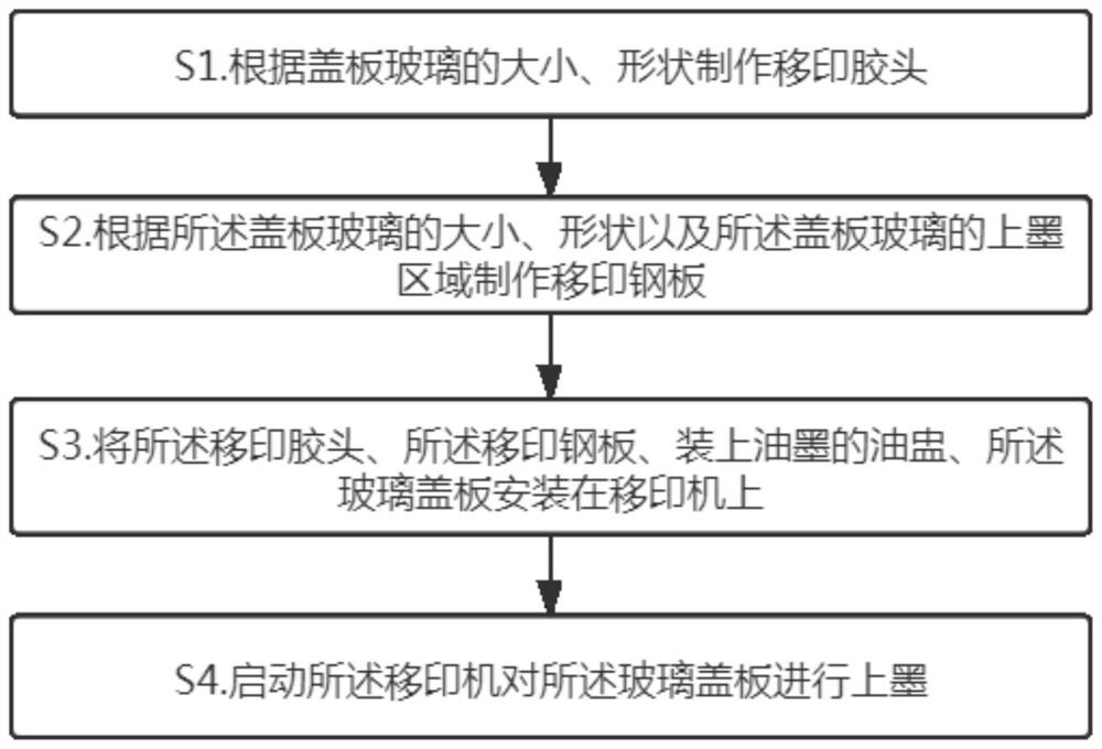
[0091] The cover glass needs to be cleaned before inking on the cover glass, and the cover glass is transferred to the inserting ultrasonic machine for cleaning. The parameters are set at 40~110℃ / 40~60kHz / 60~120s. like figure 1 As shown, it is a flow chart of the steps of a method for inking a cover glass provided by an embodiment of the present invention, including steps:

[0092] S1. Make pad printing pads according to the size and shape of the cover glass;

[0093] S2. making a pad printing steel plate according to the size and shape of the cover glass and the inked area of ​​the cover glass;

[0094] S3. Install the pad printing rubber head, the pad printing steel plate, the oil cup filled with ink, and the glass cover plate on the pad printing machine;

[0095] S4. Start the pad printer to add ink to the glass cover.

[0096] Wherein, the specific steps of making the pad printing rubb...

Embodiment 2

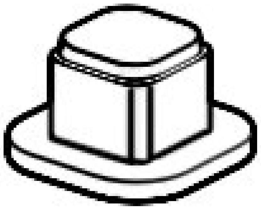
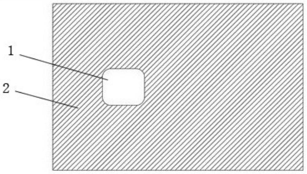
[0113] When the cover glass is the glass middle frame, the steps before pad printing and ink twice (that is, the steps before step S45) are the same as in Example 1, and the structure of the pad printing rubber head for pad printing the glass middle frame is as follows Figure 11 as shown, Figure 12 It is a schematic diagram of the etching area of ​​the steel plate, where position 1 is the etching area, and position 2 is the non-etching area. like Figure 13 Shown, inking step S4 comprises:

[0114] S41. Attach the pad printing steel plate under the oil cup; move the oil cup to the etching area of ​​the pad printing steel plate; open the oil cup to allow ink to flow into the etching area of ​​the pad printing steel plate; close said oil cup;

[0115] S42. The oil cup moves to the non-etching area of ​​the pad printing steel plate; the pad printing rubber head is pressed down at a first pressing speed, and when the pad printing rubber head is at a first distance from the pa...


PUM


Abstract

The invention relates to the field of 3D cover plate glass, and particularly discloses an inking method for cover plate glass. The method comprises the steps that S1, a pad printing rubber head is manufactured according to the size and shape of the cover plate glass; S2, a pad printing steel plate is manufactured according to the size and shape of the cover plate glass and an inking area of the cover plate glass; S3, the pad printing rubber head, the pad printing steel plate, an ink cup filled with ink and the cover plate glass are mounted on a pad printing machine; and S4, the pad printing machine is started to ink the cover plate glass. The method uses a way of pad printing inking to ink the cover plate glass, the defects of large solvent volatilization pollution and large solvent consumption in a spraying scheme are overcome, the cost is greatly reduced, the overall color effect is uniform, the ink printing position can be accurately controlled within + / - 0.03 mm, and the ink thickness is controlled within + / - 0.002 mm.

Description

technical field [0001] The invention relates to the field of 3D cover glass, in particular to an inking method for cover glass. Background technique [0002] The 3D cover glass is mainly used for the glass cover of the mobile phone, and the middle frame is mainly used for the connecting area between the front panel and the back cover of the mobile phone. Compared with the traditional 2.5D glass, ceramic cover and metal backplane, 3D glass can make the screen The display area is increased, which can prevent glare, has a strong three-dimensional effect, is more aesthetically pleasing and grasping, and has superior performance. 3D glass is expected to be widely used in screen covers and backplanes of 3C products such as tablets, smartphones, smart watches, dashboards and other wearable products in the future. With the advent of the 5G era and the era of mobile phone glass full screen, the attention of 3D cover glass and glass middle frame is constantly increasing. [0003] In...

Claims


Application Information

Patent Timeline
IPC IPC(8): B41M1/34B41M3/06B41M3/12B41M7/00B41F17/00
CPCB41F17/001B41M1/34B41M3/06B41M3/12B41M7/009
Inventor 苏向洪嘉乐蔡奕玲蔡滋萌
Owner BIEL OPTIC HUIZHOU
Learn More