
Thermal weight loss automatic detection device and system

An automatic detection and thermal weight loss technology, applied in chemical instruments and methods, crucibles, laboratory utensils, etc., can solve the problems of repeatability of results, measurement error, volume increase, etc.

Pending Publication Date: 2022-07-08
HUAZHONG UNIV OF SCI & TECH
View PDF0 Cites 0 Cited by
  • Summary
  • Abstract
  • Description
  • Claims
  • Application Information

AI Technical Summary

Problems solved by technology

[0004] At present, the burning detection still adopts the operation mode of manual clamping to move the crucible, and the crucible is moved between each station, resulting in slow correlation detection, large error, and the repeatability of the results is significantly affected by human operation, especially in the case of large detection volume. In this case, manual operation is more time-consuming and laborious, and cannot meet the requirements of quick inspection
Moreover, during the burning process, the temperature distribution of the furnace is often uneven, which usually causes the position of the crucible to change continuously during the burning process, causing measurement errors; After the volume increases, it is easy to break. On the other hand, the fixing parts will hinder the heat exchange between the crucible and the burning furnace, which will affect the heating effect.

Method used


Image

  • Thermal weight loss automatic detection device and system
  • Thermal weight loss automatic detection device and system
  • Thermal weight loss automatic detection device and system

Examples


Embodiment Construction

[0061] The thermogravimetric automatic detection device and system involved in the present invention will be described in detail below with reference to the accompanying drawings.

[0062]

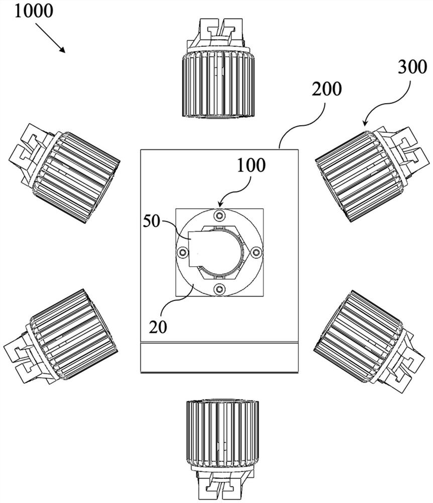
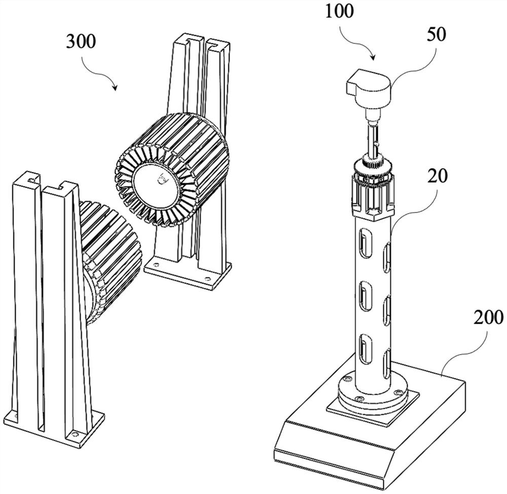
[0063] like Figures 1 to 2 As shown, the thermogravimetric automatic detection system 1000 includes a thermogravimetric automatic detection device 100, an electronic balance 200, a radiation heating device 300 and a control unit;

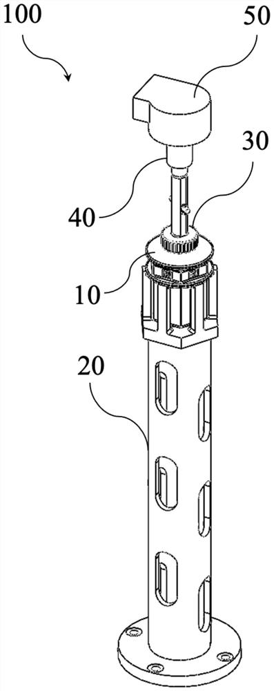
[0064] like Figures 3 to 5 As shown, the thermogravimetric automatic detection device 100 includes a crucible 10 , a supporting member 20 , a crucible connecting member 30 , a telescopic driving member 40 , a rotating member 50 and a side pressure sensor 60 .

[0065] like Figures 4 to 6 As shown, the crucible 10 includes a crucible cover 11 , a crucible base 12 and a limiting bracket 13 .

[0066] The crucible cover 11 includes a cover body 11a and two positioning pins 11b (limiting protrusions). The cover body 11a includes an upper cover part 11a-1, a...


PUM


Abstract

The invention provides an automatic thermal weight loss detection device and system, and the device comprises a crucible which comprises a crucible cover and a crucible seat, and the crucible cover comprises a cover body and two limiting protrusions protruding outwards from the two sides of the cover body; the interior of the crucible seat is used for containing a sample to be detected, the upper part of the crucible seat is matched with the crucible cover, and at least two similar G-shaped sliding chutes matched with the limiting bulges are formed in the upper part of the crucible seat; the supporting piece comprises a fixed seat, a long supporting column which is arranged on the fixed seat, is hollow inside and is provided with vent holes in the side wall, and a limiting claw which is arranged at the top of the long supporting column, is matched with the crucible and is used for limiting the crucible suspension above the balance weighing disc and in the central area of the long supporting column; the limiting claw comprises a limiting seat and a plurality of limiting columns, the limiting seat corresponds to the bottom of the crucible, the corresponding area of the limiting seat is hollowed out, the limiting columns are arranged on the limiting seat at intervals and define a restraining space for restraining the position of the crucible, and the interval areas between the limiting columns correspond to the edges of the main body part of the crucible seat; a crucible connecting piece; a telescopic driving member; a rotating member; and a side pressure sensor.

Description

technical field [0001] The invention belongs to the technical field of analysis and testing devices, and in particular relates to an automatic detection device and system for thermal weight loss. Background technique [0002] In experiments and analytical tests, it is often necessary to place the sample in a furnace body at a certain temperature for burning, so as to realize the treatment of the sample to achieve the purpose of dehydration, decomposition or removal of volatile impurities, and burning of organic matter. [0003] During the burning process at different temperatures and different conditions, the weight loss of the sample directly reflects the material composition of the sample and other compositional information. In the burning detection process, the sample to be tested is generally filled in the crucible first, and then weighed on an electronic balance to determine the quality of the sample before burning, and then the crucible containing the sample to be test...

Claims


Application Information

Patent Timeline
IPC IPC(8): G01N5/04B01L3/04B01L9/00
CPCG01N5/04B01L3/04B01L9/00
Inventor 胡松李寒剑许凯何立模韩亨达熊哲任强强徐俊江龙汪一苏胜向军
Owner HUAZHONG UNIV OF SCI & TECH
Learn More