Supercharge Your Innovation With Domain-Expert AI Agents!

Exhaust gas recirculation system with asymmetric flow

A recirculation system, asymmetric technology, applied in the field of exhaust gas recirculation system, asymmetric flow exhaust gas recirculation system, can solve the requirements of high machining accuracy and consistency, difficulty in manufacturing asymmetric supercharger, increase engine fuel consumption, etc. problems, achieve low production and installation costs, reduce economic deterioration, and reduce NOx emissions

Inactive Publication Date: 2020-11-13
山东信德玛珂增压器股份有限公司
View PDF6 Cites 0 Cited by
  • Summary
  • Abstract
  • Description
  • Claims
  • Application Information

AI Technical Summary

Problems solved by technology

[0005] The above-mentioned asymmetric channel turbocharger can be used to ensure the EGR rate. The asymmetric channel turbocharger can obtain a sufficiently high EGR rate while reducing the deterioration of economy to a certain extent. , but the asymmetric supercharger is difficult to manufacture, the processing accuracy and consistency are very high, and the cost of mass production is very high
[0006] If the exhaust throttle valve is used, the fuel consumption of the engine will be significantly increased, which is effective for achieving a sufficiently high EGR rate, but the economy is too poor

Method used


Image

  • Exhaust gas recirculation system with asymmetric flow
  • Exhaust gas recirculation system with asymmetric flow
  • Exhaust gas recirculation system with asymmetric flow

Examples


Embodiment 1

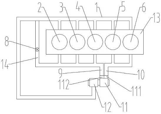
[0026] Embodiment 1: as figure 1 As shown, an exhaust gas recirculation system with asymmetric flow includes a symmetrical turbocharger, and the symmetrical turbocharger includes a turbine 11 and a compressor 12. The turbine 11 has two flow passages, and the two flows The channels are respectively a first flow channel 111 and a second flow channel 112, the second flow channel 112 of the turbine 11 is communicated with the first exhaust manifold 9, and the first flow channel 111 of the turbine 11 is communicated with the second exhaust manifold 10 , the other ends of the first exhaust manifold 9 and the second exhaust manifold 10 communicate with a certain number of exhaust manifolds corresponding to the engine 13, between the exhaust end and the intake end of the engine 13 An EGR line 14 is provided.

[0027] The number of exhaust manifolds of the engine 13 communicated with the first exhaust manifold 9 is greater than the quantity of exhaust manifolds of the engine 13 commun...

Embodiment 2

[0052] Embodiment 2: as figure 2 As shown, in the above-mentioned embodiment 1, the number of cylinders of the engine 13 can also be selected as five, and the five cylinders are respectively the first cylinder 2, the second cylinder 3, the third cylinder 4, and the fourth cylinder Body 5, the fifth cylinder body 6.

[0053] The other end of the first exhaust manifold 9 communicates with the exhaust manifolds of the first cylinder 2, the second cylinder 3, and the third cylinder 4 of the engine 13 respectively, and the second exhaust manifold 10 The other end communicates with the exhaust manifolds of the fourth cylinder 5 and the fifth cylinder 6 of the engine 13 respectively.

[0054] Such as figure 2 Shown, design like this, the waste gas discharged by the first cylinder body 2, the second cylinder body 3, and the third cylinder body 4 of engine 13 work respectively enters in the first exhaust manifold 9, and its fourth cylinder body 5, The exhaust gas discharged from t...

Embodiment 3

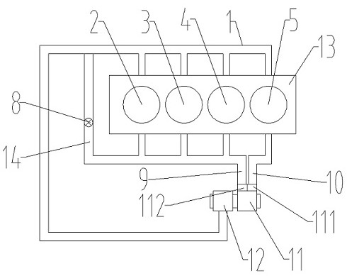
[0056] Embodiment 3: as image 3 As shown, in the above-mentioned embodiment 1, the number of cylinders of the engine 13 can also be selected from four, and the four cylinders are respectively the first cylinder 2, the second cylinder 3, the third cylinder 4, and the fourth cylinder Body 5.

[0057] The other end of the first exhaust manifold 9 communicates with the exhaust manifolds of the first cylinder 2, the second cylinder 3, and the third cylinder 4 of the engine 13 respectively, and the second exhaust manifold 10 The other end communicates with the exhaust manifold of the fourth cylinder 5 of the engine 13 .

[0058] Such as image 3 As shown, it is designed in this way, the exhaust gas discharged by the first cylinder body 2, the second cylinder body 3 and the third cylinder body 4 of the engine 13 works respectively enters in the first exhaust manifold 9, and its fourth cylinder body 5 discharges The exhaust gas enters the second exhaust manifold 10, at this time t...


PUM


Abstract

The invention discloses an exhaust gas recirculation system with asymmetric flow. The exhaust gas recirculation system comprises a symmetric turbocharger, wherein the symmetric turbocharger comprisesa turbine and a gas compressor; the turbine is provided with two flow channels, namely a first flow channel and a second flow channel; the second flow channel of the turbine communicates with a firstexhaust manifold; the first flow channel of the turbine communicates with a second exhaust manifold; the other ends of the first exhaust manifold and the second exhaust manifold communicate with a certain number of exhaust manifolds corresponding to an engine respectively; and an EGR pipeline is arranged between the first exhaust manifold and the gas inlet end of the engine. According to the exhaust gas recirculation system, the symmetric flow channel turbocharger is adopted, so that the effect of an asymmetric flow channel turbocharger is achieved, and a higher EGR rate is achieved; an EGR valve and the EGR pipeline are adopted to introduce a part of exhaust gas exhausted by the engine into the engine again, so that the EGR rate which is high enough is achieved, the emission of NOx can bereduced, and the deterioration of economy is reduced to a certain extent; and moreover, the exhaust gas recirculation system is convenient to manufacture and low in production and mounting cost, andthe using effect is greatly improved.

Description

technical field [0001] The invention relates to an exhaust gas recirculation system, in particular to an exhaust gas recirculation system with a simple structure and an asymmetric flow rate capable of effectively increasing the EGR rate, which belongs to the technical field of engines. Background technique [0002] The exhaust gas recirculation system (EGR system) is one of the effective means for the engine to reduce NOx emissions; the EGR system introduces part of the exhaust gas from the engine to the engine intake pipe, so that part of the exhaust gas from the engine is mixed with fresh air into the intake port of the engine , the exhaust gas is reintroduced into the cylinder to participate in the combustion, which can reduce the oxygen concentration and maximum combustion temperature in the cylinder, and achieve the effect of reducing NOx. [0003] In order to ensure the EGR rate, the existing technology generally uses an exhaust throttle valve or an asymmetric supercha...

Claims


Application Information

Patent Timeline
Patent Type & Authority Applications(China)
IPC IPC(8): F02M26/05F02B37/00
CPCF02B37/00F02M26/05Y02T10/12
Inventor 战强牟海峰
Owner 山东信德玛珂增压器股份有限公司
Features
  • R&D
  • Intellectual Property
  • Life Sciences
  • Materials
  • Tech Scout
  • Unparalleled Data Quality
  • Higher Quality Content
  • 60% Fewer Hallucinations
Learn More