
Central pipe provided with grid mesh and serving as draft pipe of vortex suppression device

A technology of central tube and draft tube, which is applied in the field of straight cone draft tube, can solve the problems of small cross-sectional area, difficult disassembly and replacement, and low fluid flow rate, so as to achieve stable water flow operation, reduce pressure pulsation, and increase continuous flow. The effect of time to do work

Inactive Publication Date: 2020-11-13
JIANGSU UNIV
View PDF6 Cites 2 Cited by
  • Summary
  • Abstract
  • Description
  • Claims
  • Application Information

AI Technical Summary

Problems solved by technology

However, due to the fact that the splitter is close to the inner wall of the draft tube and its unique structure and layout form, the cross-sectional area of ​​the flow is small, the local fluid velocity in the mainstream area becomes low, and backflow is easy to occur
In addition, the design of the built-in shunt plate makes it difficult to disassemble and replace when the shunt plate and the shunt tube are damaged.

Method used


Image

  • Central pipe provided with grid mesh and serving as draft pipe of vortex suppression device
  • Central pipe provided with grid mesh and serving as draft pipe of vortex suppression device
  • Central pipe provided with grid mesh and serving as draft pipe of vortex suppression device

Examples


Embodiment Construction

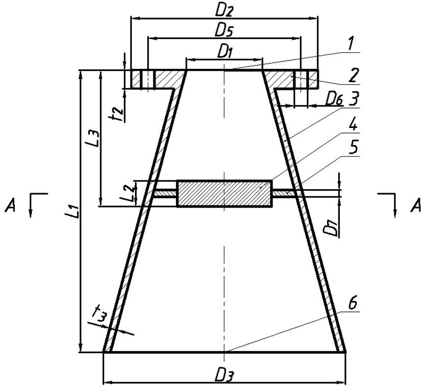
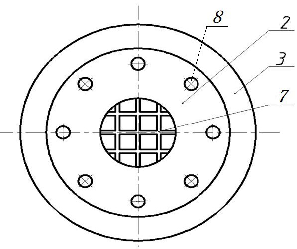
[0023] see figure 1 with figure 2 As shown, the draft tube of the present invention includes a straight cone 3, the axial section of the straight cone 3 is conical, its upper end is a small conical end, its lower end is a large conical end, and the small conical end is an open inlet 1. There is an open outlet 6 at the big end of the cone, so the straight cone 3 runs through from top to bottom. A flange structure 2 is arranged on the periphery of the upper inlet 1 of the straight cone 3, through which the flange structure 2 is fixedly connected with the outlet of the runner of the turbine and communicated with the outlet of the runner, so as to connect the draft tube to the turbine. Eight connecting holes 8 are evenly opened in the circumferential direction on the flange structure 2 , and the draft tube is fixed through these eight connecting holes 8 .

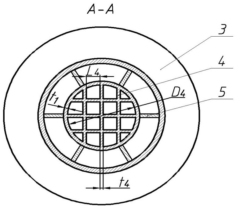
[0024] A central tube 4 is arranged inside the straight cone 3 , the profile of the central tube 4 is cylindrical, and its...


PUM


Abstract

The invention discloses a mixed flow water turbine central pipe provided with a grid mesh and serving as a draft pipe of a vortex suppression device. The central pipe comprises a right cone cylinder;a cylindrical central pipe is coaxially arranged in the right cone cylinder; six flat plates perpendicularly arranged are connected into the central pipe and are divided into two groups; each group comprises three flat plates; the three flat plates in each group are arranged at intervals in parallel; the three flat plates of the first group are perpendicularly connected with the three flat platesof the second group; the middle flat plate of three flat plates in each group is arranged in the diameter direction of the central pipe; the other two flat plates of three flat plates in each group are positioned on the two sides of the middle flat plate in the same group; the two ends of the six flat plates are fixedly connected with the inner wall of the central pipe; the six flat plates dividethe cavity of the central pipe into a grid mesh structure; and when water flows out of the outlet of a runner and flows into the central pipe, a vortex strip is damaged, the velocity circulation is reduced, and water flow rotation at the center causes negative pressure reduction, so that the strength of the velocity circulation is lowered to weaken pressure pulsation.

Description

technical field [0001] The invention relates to a mixed-flow water turbine in a fluid machine, in particular to a draft pipe part of the mixed-flow water turbine, in particular to a straight-cone draft pipe equipped with a vortex suppression device. Background technique [0002] A water turbine is a power machine that can convert the potential energy of water flow into mechanical energy. It uses water flow as a power to drive other machines to work, and belongs to the turbine machinery in fluid machinery. A water turbine will be provided with a draft tube at the outlet of its runner to collect the water flowing out of the runner and send it to the downstream river channel and recycle the remaining energy of the water flow at the outlet of the runner. When the turbine operates away from the design condition, the velocity at the runner outlet may produce a circumferential component, causing the central pressure inside the draft tube to be low and the surrounding pressure to be...

Claims


Application Information

Patent Timeline
Patent Type & Authority Applications(China)
IPC IPC(8): F03B3/18F03B11/04
CPCF03B3/18F03B11/04Y02E10/20
Inventor 何秀华张聪濮泽吉史嘉伟
Owner JIANGSU UNIV
Learn More