Signal injection topology identification device and method based on N line

A technology for identifying devices and signals, applied in the field of topology identification, can solve problems such as complex design methods, potential safety hazards, and damage to measurement equipment, and achieve the effects of ingenious design schemes, cost reduction, and rapid development

Active Publication Date: 2020-11-13
WAHLAP TECH CO LTD
View PDF10 Cites 3 Cited by
  • Summary
  • Abstract
  • Description
  • Claims
  • Application Information

AI Technical Summary

Problems solved by technology

This patent proposes a relatively advanced topology recognition technology. The disadvantages are: 1) The design method is complicated. Due to the wide bandwidth and strong penetrating ability of HPLC, it is easy to cause crosstalk, resulting in a greatly reduced recognition rate; 2) The scheme passed Inject a current signal of a specific frequency into the power line and switch it through a multi-way switch
Since the power line is a strong current, there will be a large impact and surge during the switching process, which will easily cause damage to the measuring equipment and pose a safety hazard
3) The on-site wiring of the equipment is cumbersome, the probability of wiring errors is high, and it is difficult to implement
This scheme can be called an idealized analysis method. This scheme ignores the line loss on the power grid and the power loss of the metering equipment itself, so it is difficult to form a one-to-one correspondence between the calculated electric energy comparison tables. making it difficult to derive the actual topological relationship
[0005] Chinese invention patent CN111262340A, published on June 9, 2020, a low-voltage distribution network topology identification system and method based on power line carrier N line current monitoring, the topology identification device of this patent is completed by monitoring the carrier signal on the power line N line The branch topology identification is based on the existing technology, through additional sensors, 485 communication circuits and processing circuits to realize the monitoring, transmission and processing tasks of the carrier signal. Each meter can receive instructions, but only the meter corresponding to the ID can recognize the concentrator command and return the response frame to complete the reading of data such as electric energy; 2) The two steps of signal monitoring by the carrier signal sensor are flawed, because the current stage Carrier signals are all voltage signals, carried on the power line, the response signal sent by the meter can be everywhere in the range that can be transmitted on the power line, so the sensors on the power line can receive such signals, that is, they cannot play a role. The role of accurate identification; 3) There is no specific description of the key technical characteristics of the current injection circuit

Method used


Image

  • Signal injection topology identification device and method based on N line
  • Signal injection topology identification device and method based on N line
  • Signal injection topology identification device and method based on N line

Examples


Embodiment 1

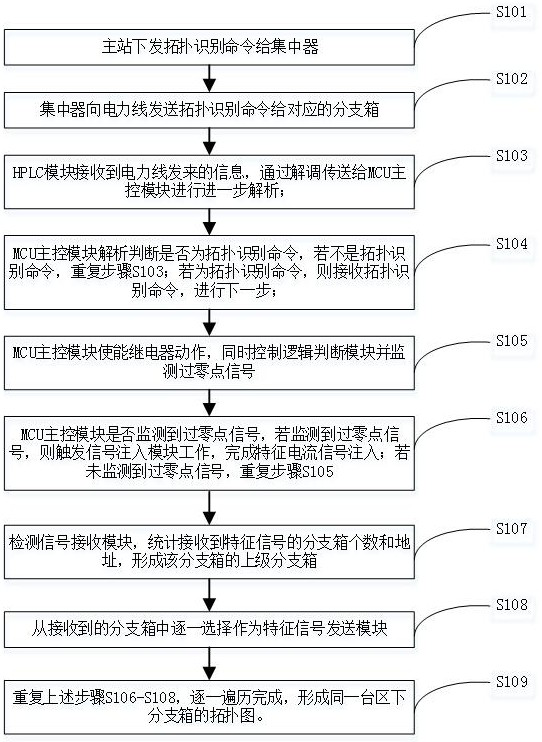
[0072] A signal injection topology identification method based on N lines, the specific topology identification process flow chart is as follows image 3 and Figure 5 shown, including the following steps:

[0073] S101: The master station issues a topology identification command to the concentrator;

[0074] S102: the concentrator sends a topology identification command to the power line to the corresponding branch box;

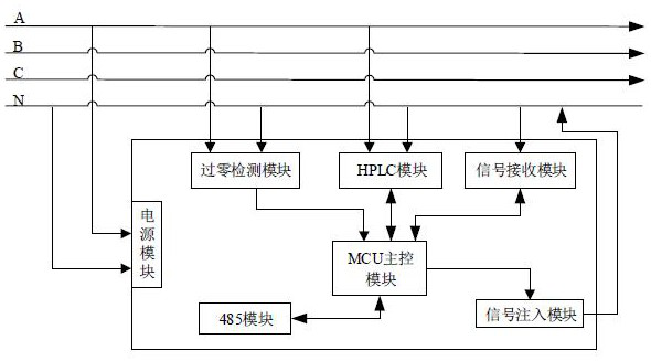
[0075] S103: The HPLC module receives the information from the power line, and sends it to the MCU main control module for further analysis through demodulation;

[0076] S104: The MCU main control module analyzes and judges whether it is a topology recognition command, if it is not a topology recognition command, repeat step S103; if it is a topology recognition command, then receives the topology recognition command, and proceeds to the next step;

[0077] S105: The MCU main control module enables the relay to act, and at the same time controls the logi...

Embodiment 2

[0087] A signal injection topology identification method based on N lines, the specific topology identification process flow chart is as follows Figure 4 and Figure 5 shown, including the following steps:

[0088] S201: The master station issues a topology identification command to the concentrator;

[0089] S202: the concentrator sends a topology identification command to the power line to the corresponding branch box;

[0090] S203: The HPLC module receives the information sent by the power line, and sends it to the MCU main control module for further analysis through demodulation;

[0091] S204: The MCU main control module analyzes and judges whether it is a topology recognition command, if it is not a topology recognition command, repeat step S203; if it is a topology recognition command, then receives the topology recognition command, and proceeds to the next step;

[0092] S205: The MCU main control module enables the relay to act, and at the same time controls the ...

Embodiment 3

[0102] A signal injection topology identification method based on N lines, the specific topology identification process flow chart is as follows Figure 6 shown, including the following steps:

[0103] S301: The master station issues a topology identification command to the concentrator;

[0104] S302: The concentrator sends a topology identification command to the power line to the corresponding branch box (each branch box has a corresponding unique ID identification number);

[0105] S303: The HPLC module receives the information sent by the power line, and sends it to the MCU main control module for further analysis through demodulation;

[0106]S304: The MCU main control module analyzes and judges whether it is a topology recognition command, and if it is not a topology recognition command, repeat step S303; if it is a topology recognition command, then receives the topology recognition command, sends a characteristic current injection signal, and completes the characteri...


PUM


Abstract

The invention provides a signal injection topology identification device and method based on an N line. The device comprises a power supply module, an MCU main control module, and a zero-crossing detection module, an HPLC module, a signal receiving module, a signal injection module and a 485 module which are connected with the MCU main control module, according to the scheme, a branch box can be conveniently and rapidly accessed, topology identification of the branch box and an electric energy meter under a transformer area is realized, troubleshooting and locking of fault points are facilitated, electric energy supply of the fault points is cut off at the first time, faults are timely maintained, normal and efficient supply of electric power is ensured, and rapid development of ubiquitouselectric power Internet of Things can be effectively promoted.

Description

technical field [0001] The present invention relates to the technical field of topology identification, in particular to an N-wire-based signal injection topology identification device and method. Background technique [0002] In 2019, the State Grid Corporation of China put forward the strategic goal of "three types, two networks, and world-class". The ubiquitous power Internet of Things revolves around all links of the power system, fully applies modern information technologies such as mobile Internet and artificial intelligence, and advanced communication technologies to realize the interconnection of all things and human-computer interaction in all links of the power system. It has comprehensive state perception, efficient information processing, and convenient application. Intelligent service system with flexible features. Many new technologies have been proposed in the process of comprehensively sensing the distribution of network-connected devices. The following pat...

Claims


Application Information

Patent Timeline
Patent Type & Authority Applications(China)
IPC IPC(8): G01R35/04G01R19/175
CPCG01R19/175G01R35/04
Inventor 韩鹏宁骞卢玉凤高春梅任旭潘毅
Owner WAHLAP TECH CO LTD
Why Eureka
Try Eureka