Double-layer full-pitch winding coreless linear permanent magnet synchronous motor

A permanent magnet synchronous motor and full-pitch winding technology, which is applied to the shape/style/structure of synchronous machine components, windings, and winding conductors, can solve problems such as poor insulation characteristics and poor heat dissipation performance, and improve the strength of the primary structure And, improve the winding factor and thrust density, reduce the effect of eddy current loss

Active Publication Date: 2020-11-13
HARBIN INST OF TECH
View PDF3 Cites 2 Cited by
  • Summary
  • Abstract
  • Description
  • Claims
  • Application Information

AI Technical Summary

Problems solved by technology

[0004] The present invention aims to solve the problem that the existing double-sided secondary coreless structure linear permanent magnet synchronous motor adopts an integer slot single-layer winding, the two effective sides of the coil are in the same plane, the ends of th...

Method used


Image

  • Double-layer full-pitch winding coreless linear permanent magnet synchronous motor
  • Double-layer full-pitch winding coreless linear permanent magnet synchronous motor
  • Double-layer full-pitch winding coreless linear permanent magnet synchronous motor

Examples


specific Embodiment approach 1

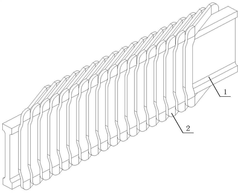
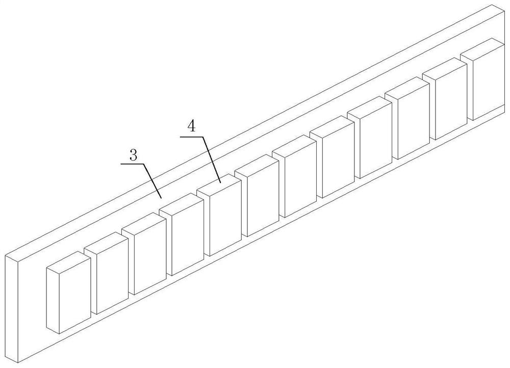
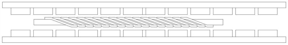
[0029] Specific embodiment one: reference Figure 1 to Figure 5 To describe this embodiment in detail, the double-layer whole-pitch winding ironless linear permanent magnet synchronous motor described in this embodiment includes one primary, two secondary and base 7. The two secondary are located on both sides of the primary, and an air gap is formed between the primary and the secondary. The two secondary bottoms are connected by the base 7. The secondary includes: a plate 3 and 12 permanent magnets 4, the 12 permanent magnets 4 are alternately arranged along the motor movement direction N and S poles and fixed on the air gap side of the yoke plate 3, so that the secondary 12 magnetic poles. The magnetizing directions of the permanent magnets 4 facing each other in the two secondary stages are the same.

[0030] The primary includes: a substrate 1, 18 coils 2 and an output board 5. The coil 2 is rectangular, and all four corners are provided with arc-shaped chamfers. The 18 ...

specific Embodiment approach 2

[0032] Specific embodiment two: reference Image 6 with 7 Detailed description of this embodiment, this embodiment is a further description of the double-layer full-pitch winding coreless linear permanent magnet synchronous motor described in the first embodiment. In this embodiment, the primary is a liquid cooling structure. Specifically:

[0033] The upper end of the base plate 1 is provided with a "U"-shaped cooling pipe 8 arranged along the three sides of the top end of the base plate 1. The cooling pipe 8 is located between the top end of the base plate 1 and the inner ring surface of the top end of the coil 2.

[0034] The double-layer full-pitch winding coreless linear permanent magnet synchronous motor in this embodiment adopts direct liquid cooling at the coil end, which improves the cooling capacity and output capacity of the motor.

specific Embodiment approach 3

[0035] Specific embodiment three: reference Figure 8 with 9 Detailed description of this embodiment, this embodiment is a further description of the double-layer full-pitch winding coreless linear permanent magnet synchronous motor described in the first embodiment. In this embodiment, the primary is a liquid cooling structure. Specifically:

[0036] Four cooling liquid flow channels 9 are opened along the length of the substrate 1, and the four cooling liquid flow channels 9 are located on the upper and lower parts of the substrate 1 in pairs.

[0037] The double-layer full-pitch winding coreless linear permanent magnet synchronous motor in this embodiment adopts direct liquid cooling at the coil end, which improves the cooling capacity and output capacity of the motor.


PUM


Abstract

The invention discloses a double-layer full-pitch winding coreless linear permanent magnet synchronous motor, and relates to the field of motors. The invention aims to solve the problems that the existing bilateral secondary coreless structure linear permanent magnet synchronous motor adopts an integer slot single-layer winding, two effective edges of a coil are in the same plane, the end parts ofthe coil are overlapped, and the insulation characteristic is poor, and the problem that the heat dissipation performance is poor because the winding is completely packaged in epoxy resin with a lowheat conductivity coefficient. By adopting the double-layer full-pitch winding, the winding factor and the thrust density are improved, the thrust fluctuation of the motor and the eddy-current loss ofthe secondary permanent magnet are reduced, the non-overlapping of the end parts of the coils is realized, and the insulating property of the winding is improved. The end part of the coil is directlycooled by liquid, so that the cooling capacity and output capacity of the motor are improved. The winding substrate is made of a high-strength material, so that the primary structural strength of themotor and the armature coil arrangement precision are improved. By reasonably designing the size of the secondary iron core near the end part of the winding, the leakage reactance of the winding is increased, the current harmonic is reduced, and the secondary permanent magnet eddy-current loss is reduced.

Description

Technical field [0001] The invention belongs to the field of motors, and particularly relates to the primary of a linear permanent magnet synchronous motor. Background technique [0002] Such as Figure 10 to 12 Shown is a schematic structural diagram of a linear permanent magnet synchronous motor with a bilateral secondary coreless structure in the prior art. The secondary of the motor is composed of a yoke plate and a flat plate-shaped permanent magnet. The permanent magnets are magnetized in parallel in a direction perpendicular to the direction of movement. The permanent magnets are arranged alternately in the direction of movement N and S and fixed on the air gap side of the secondary yoke plate. The magnetizing direction of the permanent magnets on the bilateral secondary is the same, forming a series magnetic circuit, and the primary is located between the two secondary. The normal component of the air gap magnetic field generated by the permanent magnet passes through the...

Claims


Application Information

Patent Timeline
IPC IPC(8): H02K3/28H02K3/42H02K3/24H02K3/47H02K9/19H02K1/20H02K41/03H02K21/02H02K16/02H02K1/27
CPCH02K3/28H02K3/42H02K3/24H02K3/47H02K9/19H02K1/20H02K41/031H02K21/02H02K16/02H02K1/2793H02K2213/03H02K2201/03
Inventor 寇宝泉王硕张浩泉张赫
Owner HARBIN INST OF TECH
Why Eureka
Try Eureka