Low-frequency broadband efficient array forming structure based on bent disc transducer

A transducer and disc technology, applied in the field of low-frequency broadband high-efficiency array structure, can solve the problems of low power density, low average electro-acoustic conversion efficiency, and narrow working bandwidth in a wide frequency band, so as to avoid non-uniform distribution, Improve the electro-acoustic conversion efficiency and the effect of large effective radiation area

Inactive Publication Date: 2020-11-13
THE 715TH RES INST OF CHINA SHIPBUILDING IND CORP
View PDF6 Cites 2 Cited by
  • Summary
  • Abstract
  • Description
  • Claims
  • Application Information

AI Technical Summary

Problems solved by technology

[0004] Because it is in the bending vibration mode, the bending disc transducer and its conventional array method (half-wavelength line array) have the following disadvantages: the electroacoustic efficiency at the resonance point is high, but the working bandwidth is generally narrow, and at the resonance point The electro-acoustic efficiency drops significantly near the point, so the power density in the broadband is low
With the development of underwater acoustic detection technology in the direction of low frequency, broadband and high power, the curved disc transducer and its conventional array method are difficult to meet the development needs of low-frequency underwater acoustic remote detection and communication technology.
Because it works in the first-order bending vibration mode, the working bandwidth of the bending disc transducer and its conventional array is narrow, and the average electro-acoustic conversion efficiency in the wide frequency band is low, and its resonance frequency is determined by the material and structural design , the resonant frequency cannot be lowered by the mutual radiation effect

Method used


Image

  • Low-frequency broadband efficient array forming structure based on bent disc transducer
  • Low-frequency broadband efficient array forming structure based on bent disc transducer
  • Low-frequency broadband efficient array forming structure based on bent disc transducer

Examples


Embodiment Construction

[0021] The present invention will be described in detail below in conjunction with accompanying drawing:

[0022] The present invention focuses on solving the problems of high resonant frequency, narrow working bandwidth and low electroacoustic efficiency of the curved disk transducer and its line array, starting from the working mechanism of the close-arranged array mutual radiation of the curved disk transducer , combined with the actual application requirements, an array design method that can effectively reduce the resonance frequency of the transmitting array, expand the working bandwidth of the curved disk transducer, and improve the electroacoustic efficiency is proposed.

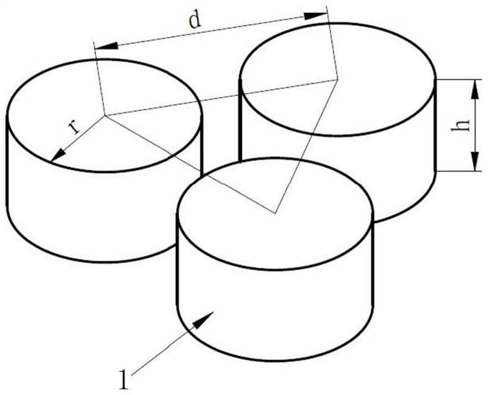
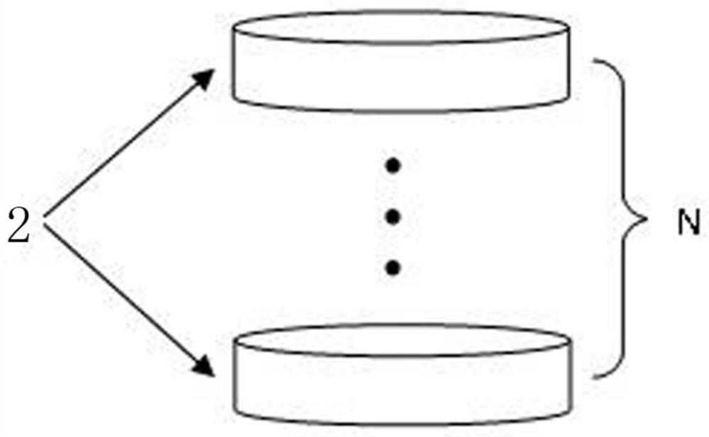
[0023] The emission array includes: multiple sets of transducer units 1;

[0024] The emission array is composed of multiple sets of identical transducer units 1 arranged at equal intervals in the horizontal direction; the postures of the transducer units in the emission array are consistent; the aco...


PUM


Abstract

The invention discloses a low-frequency broadband efficient array forming structure based on a bent disc transducer, which mainly comprises a transmitting array. The transmitting array comprises a plurality of groups of transducer units, the transmitting array is formed by arranging a plurality of groups of same transducer units at equal intervals in the horizontal direction, and the postures of the transducer units in the transmitting array are consistent; the acoustic center distance between the transducer units is not greater than the half wavelength of the transducer units at a resonant frequency point, and therefore the near-field mutual radiation influence on each group of transducer units is kept consistent; each transducer unit is formed by arranging one or more bent disc transducers in the axial direction. Radiation impedance of the bent disc transducers can be changed by arraying the bent disc transducers according to a specific arraying mode, and therefore resonant frequencyof a transmitting array is reduced; working bandwidth is expanded, electro-acoustic efficiency is improved; the transmitting array is enabled to meet development requirements of a future maneuveringdetection system.

Description

technical field [0001] The invention relates to the field of curved disk transducers, and mainly relates to a low-frequency broadband high-efficiency array structure based on curved disk transducers. Background technique [0002] With the continuous implementation of the ocean power strategy, the underwater acoustic technology has been continuously improved, and the sonar equipment platform has shown diversified development. Among them, mobile deployment underwater acoustic detection systems such as towed detection sonar, airborne detection sonar and UUV / AUV are developing most rapidly. The mobile deployment underwater acoustic detection system has attracted much attention because of its advantages of flexibility, convenience, fast response and being away from platform vibration. The future development prospects and demands are extremely considerable. [0003] The installation platform of the mobile deployment underwater acoustic detection system has a small space and a lig...

Claims


Application Information

Patent Timeline
Patent Type & Authority Applications(China)
IPC IPC(8): H04R1/44G10K9/122
CPCH04R1/44G10K9/122
Inventor 任一石俞思源程启航姚纪元伍恒飞
Owner THE 715TH RES INST OF CHINA SHIPBUILDING IND CORP
Why Eureka
Try Eureka