Portable cleaning and sterilizing device for gynaecology and obstetrics nursing
A portable obstetrics and gynecology technology, which is applied in the field of portable obstetrics and gynecology nursing cleaning and disinfection devices, can solve the problems of vaginal stretching, increased workload of medical staff, incomplete cleaning and sterilization, etc., to reduce workload, High degree of automation, improvement of cleaning quality and cleaning efficiency
- Summary
- Abstract
- Description
- Claims
- Application Information
AI Technical Summary
Problems solved by technology
Method used
Image
Examples
Embodiment 1
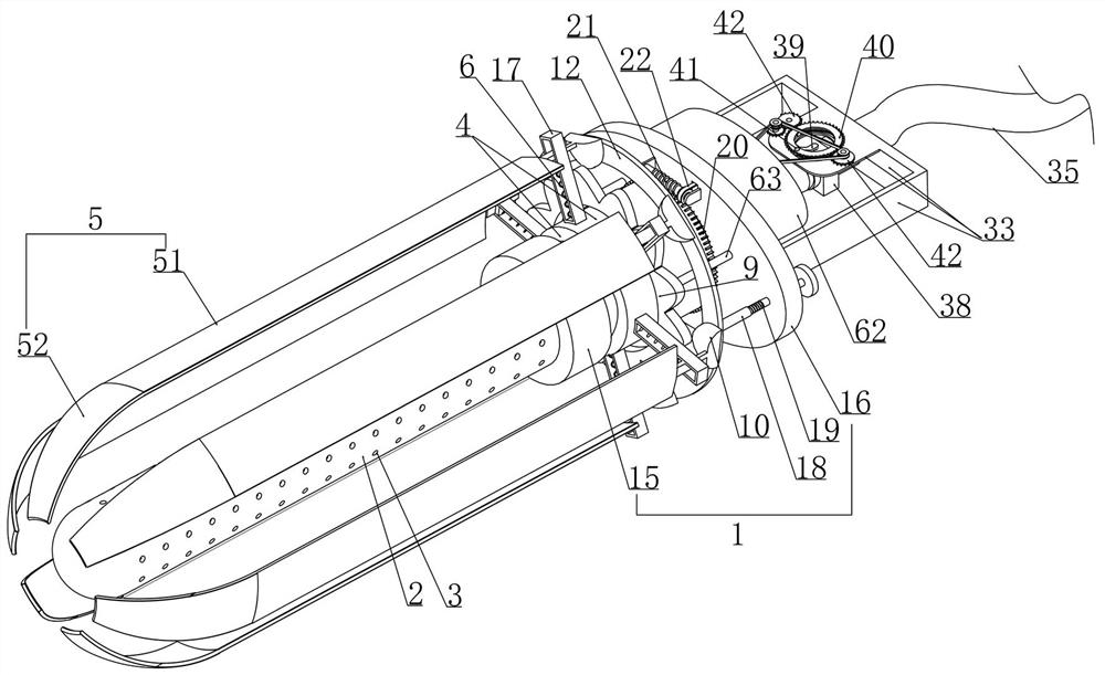
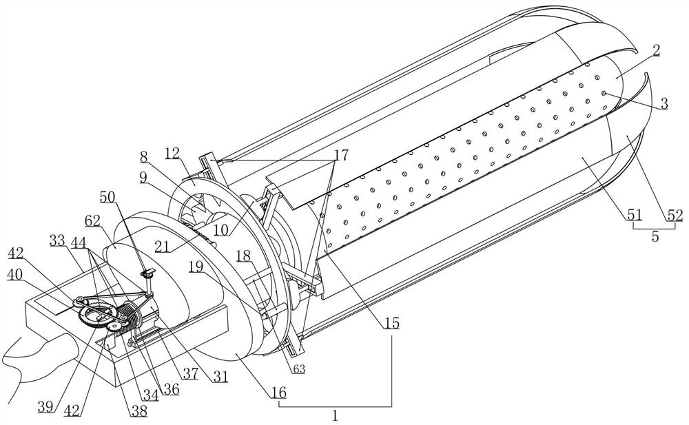
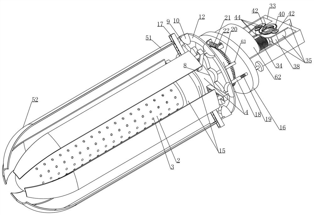
[0040] Embodiment 1, this embodiment provides a portable obstetrics and gynecology care cleaning and disinfection device, refer to the attached figure 1 As shown, including the bearing cylinder 1, it is characterized in that we rotate the coaxial center on the lateral side of the bearing cylinder 1 and install the cleaning pipe 2 connected with it, and we are uniformly arranged with several water outlets on the outer surface of the cleaning pipe 2 3. The cleaning pipe 2 is connected to the water pipe 7 which is arranged coaxially with the bearing cylinder 1 and is rotatably installed in the bearing cylinder 1. We connect the water pipe 7 to a constant pressure water supply device (the constant pressure water supply device may include a liquid storage Tanks, control systems, and water pumps, the working principle is: automatically adjust the operating speed according to changes, so that the outlet pressure of the water pump remains constant. Since the constant pressure water sup...
Embodiment 2
[0048] Embodiment 2, on the basis of embodiment 1, with reference to appended Figure 10 As shown, the carrying cylinder 1 includes a mounting cylinder 15 which is rotatably matched with the cleaning pipe 2, referring to the attached Figure 13 As shown, the installation cylinder 15 is integrally connected with an elliptical plate 16, and we have fixed a number of slide rails 17 around the outer surface of the installation frame 4 at intervals (refer to the attached Figure 8 shown in ) and make the arc-shaped expansion plate 5 radially slide and install in the corresponding slide rail 17 along the mounting bracket 4, the telescopic spring 6 is connected between the arc-shaped expansion plate 5 and the slide rail 17, refer to the attached Image 6As shown, we fix the limiting cylinder 18 on both axial sides of the interference ring 12 and set the limiting rod 19 on the side of the elliptical plate 16 facing the conflicting ring 12, which is slidingly fitted with the limiting c...
Embodiment 3
[0050] Embodiment 3, on the basis of embodiment 2, with reference to appended Figure 13 As shown, the first transmission device includes: the mounting bracket 4 faces the elliptical plate 16 side of the coaxial core sleeve inherent worm wheel ring 20 and the worm wheel ring 20 is equipped with a worm 21 that is installed in rotation on the elliptical plate 16 (due to the one-way transmission of the worm gear and worm) The principle is that when the worm 21 does not rotate, even if the mounting bracket 4 is subjected to an external force, it will not rotate. When we set the worm 21, we make it and the oval plate 16 rotate with a friction damper to increase the size of the worm 21. rotation frictional resistance to prevent the worm 21 from rotating when subjected to unnecessary external force), refer to the attached Figure 14 As shown, the worm 21 is connected with the first pulley set 22 and the first pulley set 22 drives the bevel gear set 23 arranged on the oval plate 16, t...
PUM
 Abstract
Description
Claims
Application Information
 - R&D
- Intellectual Property
- Life Sciences
- Materials
- Tech Scout
- Unparalleled Data Quality
- Higher Quality Content
- 60% Fewer Hallucinations
Browse by: Latest US Patents, China's latest patents, Technical Efficacy Thesaurus, Application Domain, Technology Topic, Popular Technical Reports.
© 2025 PatSnap. All rights reserved.Legal|Privacy policy|Modern Slavery Act Transparency Statement|Sitemap|About US| Contact US: help@patsnap.com


