Large vertical shaft hammering type crusher

A crusher and vertical shaft technology, which is applied in the field of large vertical shaft hammer crushers to achieve good crushing effect, prevent clogging and increase the discharge rate.

Inactive Publication Date: 2020-11-17
ZAOZHUANG SNKSAN INTELLIGENT MACHINERY CO LTD
View PDF7 Cites 2 Cited by
  • Summary
  • Abstract
  • Description
  • Claims
  • Application Information

AI Technical Summary

Problems solved by technology

[0003] The present invention provides a large vertical shaft hammer crusher, which solves the problems in the above-mentioned background technology

Method used


Image

  • Large vertical shaft hammering type crusher
  • Large vertical shaft hammering type crusher
  • Large vertical shaft hammering type crusher

Examples


Embodiment 1

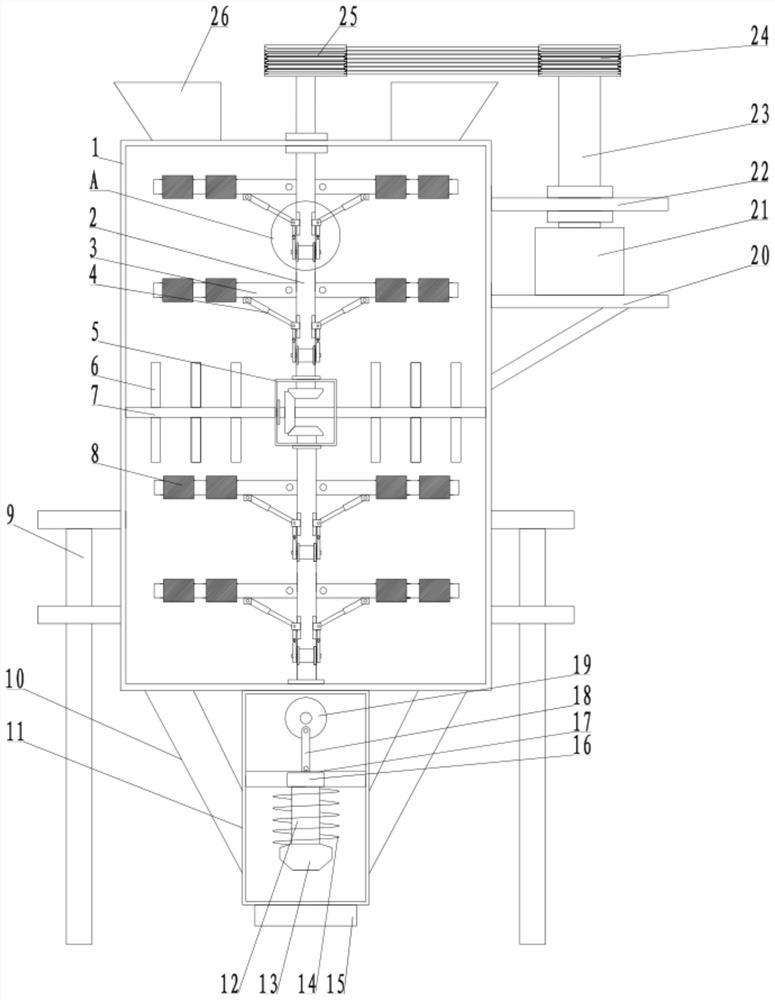
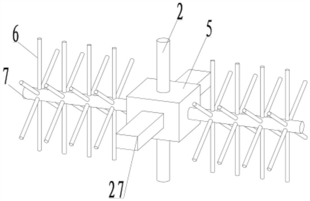
[0021] see Figure 1-4 , a large vertical shaft hammer crusher, comprising a crushing box 1, a transmission box 5 is arranged in the crushing box 1, the front and rear sides of the transmission box 5 are fixedly connected with installation rods 27, and the two sides of the installation rod 27 are connected to the front and rear of the crushing box 1. The side walls are fixedly connected, the top and bottom of the transmission box 5 are rotatably connected to the rotating column 2, the two sides of the rotating column 2 are hingedly connected to the crushing rod 3, and the crushing rod 3 is fixedly connected to the crushing hammer 8 on the side away from the rotating column 2, and the crushing rod 3 The bottom is hingedly connected to the elastic telescopic rod 4, and one side of the rotating column 2 below the elastic telescopic rod 4 is provided with a chute 28, and the mounting block 29 is slidably connected on the chute 28, and one side of the mounting block 29 is hingedly c...

Embodiment 2

[0027] see Figure 1-4 , the other content of this embodiment is the same as that of Embodiment 1, the difference is that: the two ends of the crushing column 7 pass through the side wall of the transmission box 5, extend to the side wall of the crushing box 1, and both sides are connected to the side wall of the crushing box 1 Rotationally connected, the crushing columns 7 on both sides of the transmission box 5 are fixedly connected to the crushing blades 6 .

[0028] In the implementation process of the present invention, the material is put into the crushing box 1 from the feed pipe 26, the drive motor 21 is started, and under the action of the belt, the rotating column 2 is driven to rotate. Driven by the cam 32 on the motor 33, the installation block 29 moves back and forth in the chute 28, and then drives the elastic telescopic rod 4 to move, and the crushing hammer 8 swings in a small range. When crushing, the flexibility of the device is increased, and the crushing ef...


PUM


Abstract

The invention discloses a large vertical shaft hammering type crusher, and relates to the technical field of crushers. The crusher comprises a crushing box, a transmission box is arranged in the crushing box, the front and rear sides of the transmission box are fixedly connected with mounting rods, the two sides of the mounting rods are fixedly connected with the front and rear side walls of the crushing box, and the top and bottom of the transmission box are rotatably connected with rotating columns. Crushing rods are hinged to the two sides of each rotating column, crushing hammers are fixedly connected to the sides, away from the rotating columns, of the crushing rods, elastic telescopic rods are hinged to the bottoms of the crushing rods, sliding grooves are formed at the sides, belowthe elastic telescopic rods, of the rotating columns, mounting blocks are slidably connected to the sliding grooves, and one sides of the mounting blocks are hinged to the elastic telescopic rods; andthe bottoms of the mounting blocks are fixedly connected with mounting columns, the bottoms of the mounting columns are rotatably connected with pulleys, double-shaft motors are fixedly connected with the positions, below the sliding grooves, in the rotating columns, and the ends of output shafts of the double-shaft motors are fixedly sleeved with cams. The crusher is simple in structure, reasonable in design, convenient to operate and use, good in crushing effect and high in working efficiency.

Description

technical field [0001] The invention relates to the technical field of crushers, in particular to a large vertical shaft hammer crusher. Background technique [0002] Vertical shaft hammer crusher is suitable for crushing limestone, clinker, coal and other ores in building materials, mining, metallurgy and chemical industry. It has large production capacity, high crushing ratio, low energy consumption, good sealing performance, stable operation and convenient maintenance. Vertical shaft hammer crusher, but most of the hammer heads in the current crusher rotate in the same direction to impact the material, causing the material to be crushed. At that time, the material will rotate in the same direction after being impacted, so that the next hammering crushing effect Reduced, the material cannot be crushed well, and the general crusher is not equipped with an auxiliary discharge device. When the material blocks the discharge port, it cannot be discharged normally. Manual dredgi...

Claims


Application Information

Patent Timeline
Patent Type & Authority Applications(China)
IPC IPC(8): B02C13/14B02C13/30B02C13/26B02C13/286
CPCB02C13/14B02C13/26B02C13/286B02C13/30B02C2013/28609
Inventor 孙法虎孙启祥马驰
Owner ZAOZHUANG SNKSAN INTELLIGENT MACHINERY CO LTD
Why Eureka
Try Eureka