Engine crankshaft surface heat treatment method

A surface heat treatment and engine technology, applied in heat treatment furnaces, heat treatment equipment, furnaces, etc., can solve the problems of high rejection rate, difficult to spray uniformly, and large cross-section size of sampling parts, and achieves a sealing effect, avoids pollution, and is easy to disassemble. Effect

Active Publication Date: 2020-11-17
河北福昊机械制造有限公司
View PDF10 Cites 0 Cited by
  • Summary
  • Abstract
  • Description
  • Claims
  • Application Information

AI Technical Summary

Problems solved by technology

[0003] Due to the complex shape of the engine crankshaft and the large cross-sectional size of the sampling part, it is difficult to spray water evenly during the spray cooling process, and the comprehensive mechanical performance requirements of the cooling device are relatively high. The following problems: a. During the cooling process of the engine crankshaft, it is difficult to ensure that the surface of the engine crankshaft with complex shapes is evenly sprayed with cooling water. The difference in cooling time of each part of the engine crankshaft may cause excessive cracking tendency of the crankshaft, resulting in a high scrap rate , and it is impossible to control the flow of coolant in real time according to the cooling process, so that the engine crankshaft can achieve a stable cooling effect; The coolant is filtered and collected, and the residue left in the coolant will make it difficult to reuse the coolant

Method used


Image

  • Engine crankshaft surface heat treatment method
  • Engine crankshaft surface heat treatment method
  • Engine crankshaft surface heat treatment method

Examples


Embodiment Construction

[0030] In order to make the technical problems, technical solutions and beneficial effects to be solved by the present invention clearer, the present invention will be further described in detail below in conjunction with the accompanying drawings and embodiments. It should be understood that the specific embodiments described here are only used to explain the present invention, not to limit the present invention.

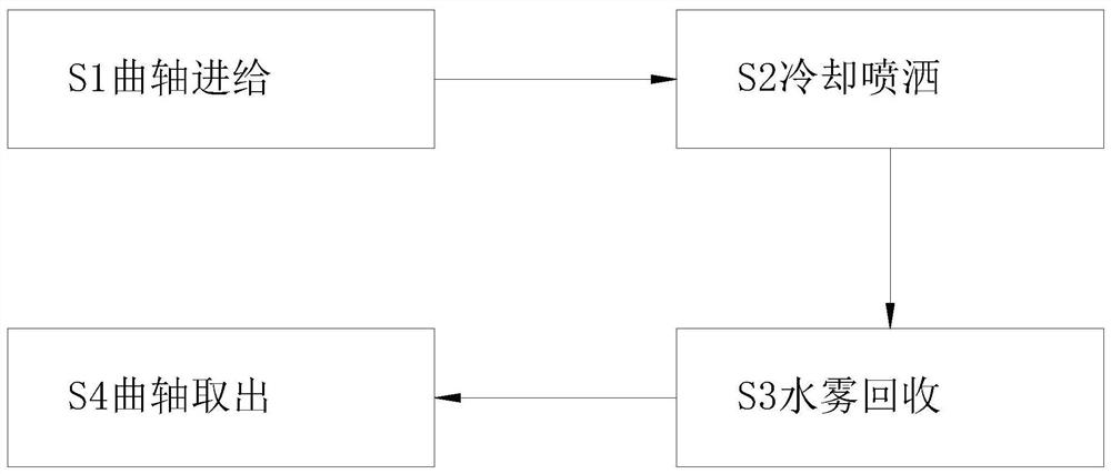
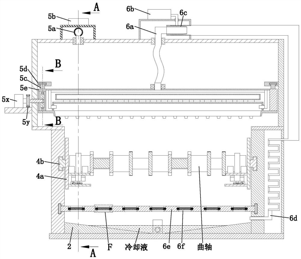
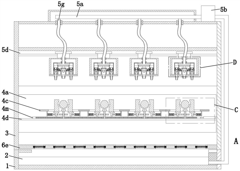
[0031]Refer to 1-8, a method for heat treatment of the surface of an engine crankshaft, which uses a surface heat treatment device for an engine crankshaft, which includes a cooling box 1, a liquid storage tank 2, a movable plate 3, and a clamping mechanism 4 , Spray mechanism 5 and water mist recovery mechanism 6, when adopting above-mentioned engine crankshaft surface heat treatment device to carry out forming processing operation to cold-rolled plate, specific method is as follows:

[0032] S1. Crankshaft feeding: Put the engine crankshaft after heat treatment i...


PUM


Abstract

The invention relates to an engine crankshaft surface heat treatment method. According to the method, an engine crankshaft surface heat treatment device is used, the engine crankshaft surface heat treatment device comprises a cooling box, a liquid storage tank, a movable plate, a clamping mechanism, a spraying mechanism and a water mist recovery mechanism, and when the engine crankshaft surface heat treatment device is used for carrying out forming machining operation on a cold-rolled plate, the specific method comprises the following steps that S1, crankshaft feeding is conducted; S2, coolingand spraying are conducted; S3, water mist recovery is conducted; and S4, a crankshaft is taken out. According to the engine crankshaft surface heat treatment method, the problems existing in the existing engine crankshaft surface heat treatment that it is difficult to guarantee that cooling water is evenly sprayed on the surface of an engine crankshaft in a complex shape in the engine crankshaftcooling process, consequently, the crankshaft has an overlarge cracking tendency, the reject ratio of waste products is increased, the flow of the cooling liquid cannot be controlled in real time according to the cooling process, and the engine crankshaft cannot achieve a stable cooling effect can be solved.

Description

technical field [0001] The invention relates to the technical field of engine crankshafts, in particular to a surface heat treatment method for engine crankshafts. Background technique [0002] The engine crankshaft is generally made of special 42CrMoA steel. After being forged and formed and kept warm for a period of time, it needs to be taken out of the furnace and cooled in the air or sprayed with water, sprayed or blown for metal heat treatment. [0003] Due to the complex shape of the engine crankshaft and the large cross-sectional size of the sampling part, it is difficult to spray water evenly during the spray cooling process, and the comprehensive mechanical performance requirements of the cooling device are relatively high. The following problems: a. During the cooling process of the engine crankshaft, it is difficult to ensure that the surface of the engine crankshaft with complex shapes is evenly sprayed with cooling water. The difference in cooling time of each p...

Claims


Application Information

Patent Timeline
Patent Type & Authority Applications(China)
IPC IPC(8): C21D9/30C21D1/06
CPCC21D1/06C21D9/30Y02P10/20
Inventor 张涛
Owner 河北福昊机械制造有限公司
Why Eureka
Try Eureka