Battery

A battery and micro-battery technology, applied in secondary battery manufacturing, battery pack parts, circuits, etc., can solve problems such as difficulty in passing large current, difficulty in realizing automation, difficulty in battery assembly, etc., so as to improve heat dissipation capacity and realize automatic production , the effect of simple assembly

Active Publication Date: 2020-11-17
SHENZHEN EASY POWER STORE TECH CO LTD
View PDF7 Cites 6 Cited by
  • Summary
  • Abstract
  • Description
  • Claims
  • Application Information

AI Technical Summary

Problems solved by technology

[0002] Existing batteries generally connect the pole piece and the pole shell through tabs. At present, the tabs and the pole shell are generally connected by welding, but the welding process is relatively complicated, and it is prone to false welding. It is difficult to pass a large current; in addition, the battery will heat up during use and cause expansion. The existing battery is usually designed with a structure that can expand and contract along the direction of the two electrodes, but it is not suitable for some usage scenarios that are sensitive to battery expansion. suitable for use with this type of battery
In addition, batteries are becoming more and more common in daily life, such as IoT batteries, hearing aid batteries, Bluetooth headset batteries, etc. Due to their small size, battery assembly is becoming more and more difficult, the pass rate is low and automation is difficult, and the cost is high.

Method used


Image

  • Battery
  • Battery
  • Battery

Examples


Embodiment 1

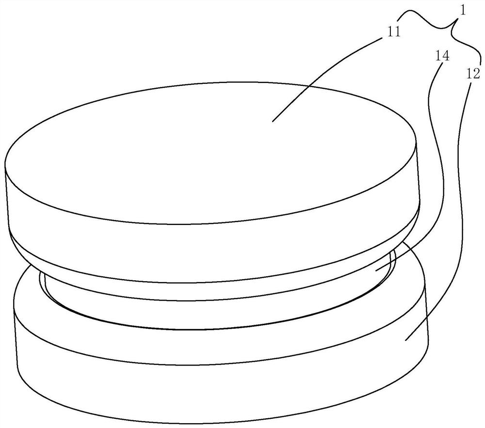
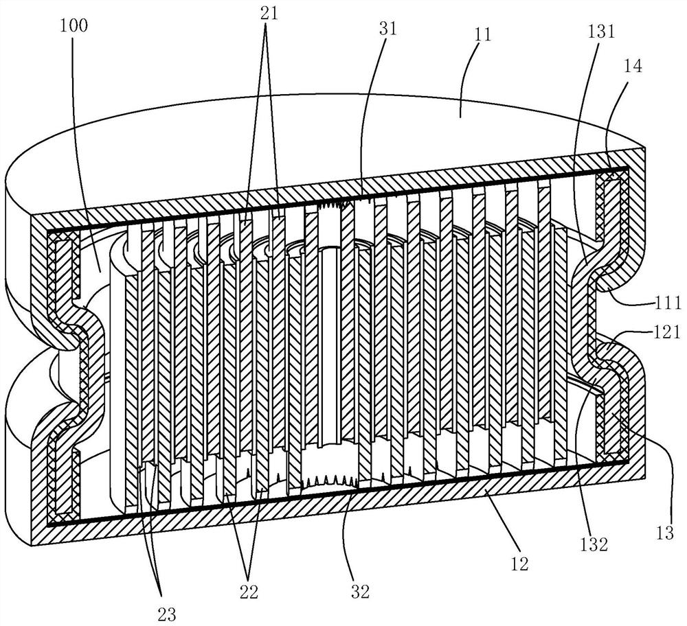
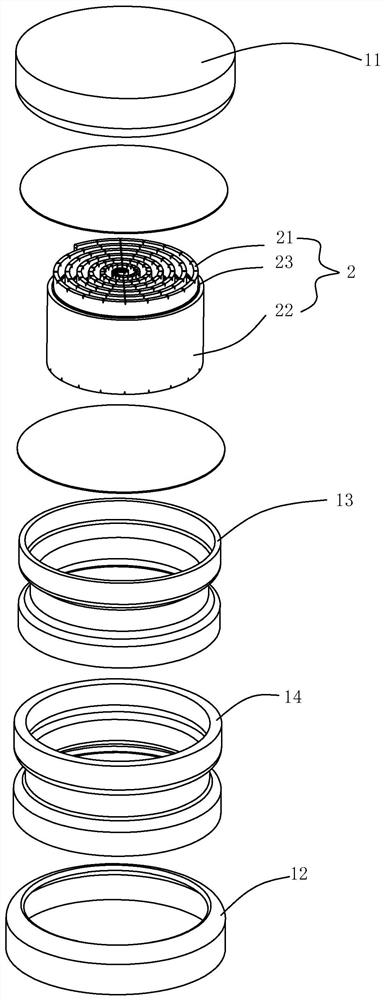
[0030] like Figure 1 to Figure 3 As shown, a battery of this embodiment, the micro battery includes a casing 1 and a battery cell 2, and the casing 1 includes: a first pole casing 11 made of a conductive material, a second pole casing 11 made of a conductive material Diode shell 12 and base shell 13 made of conductive material, the first pole shell 11 is sealed and connected to one end of the base shell 13, and the second pole shell 12 is sealed and connected to the other end of the base shell 13, An insulating layer 14 made of insulating material is provided between the base shell 13 and the first pole shell 11 and the second pole shell 12. The first pole shell 11, the second pole shell 12 and the base shell 13 There is a cavity 100 for accommodating the electric core 2 therebetween, the electric core 2 includes a first pole piece 21 and a second pole piece 22 wound with each other, and the first pole piece 21 and the second pole piece 22 Next to each other, and a separator...

Embodiment 2

[0036] like Figure 4 to Figure 6 As shown, the difference between this embodiment and Embodiment 1 is that: this embodiment is provided with an outwardly bent boss A112 on the first pole shell 11; The boss B122; this design can facilitate automatic assembly.

Embodiment 3

[0038] like Figure 7 to Figure 9 As shown, the difference between this embodiment and Embodiment 1 is that: the first pole shell 11 is provided with a reinforcement part A113 for improving the sealing performance between the first pole shell 11 and the upper edge of the base shell 13, so The reinforcement part A113 is in a "U" shape, and the upper edge of the base case 13 is stuck in the reinforcement part A113; The reinforcing part B123 with sealing performance between them, the reinforcing part B123 is in the shape of "U", and the lower end edge of the base shell 13 is stuck in the reinforcing part B123. Adopting this design can improve the sealing performance between the first pole shell, the second pole shell and the two ends of the base shell, improve the effectiveness and strength of the seal, and reduce the proportion of battery leakage.


PUM


Abstract

According to the battery disclosed by the invention, the shoulder A and the shoulder B which are bent outwards are arranged in the middle of the base shell, so that when the battery is heated and gasin the battery expands, the gas can expand towards two ends of a cavity, a pressure relief effect can be achieved, and the phenomenon of telescopic expansion towards two electrodes can be avoided; meanwhile, the heat dissipation area of the shell can be increased, and the heat dissipation capacity is improved; the sealing performance of the battery can be improved by the sealing and flanging process, the strength of the first pole shell and the second pole shell can be improved, and the overall structural strength of the battery is improved; a first pole piece and a second pole piece are woundinto a whole, the upper end face of the first pole piece is electrically connected with a first pole shell, and the lower end face of the second pole piece is electrically connected with a second pole shell; by the adoption of the connecting mode, welding is not needed, the process can be simplified, cost is reduced, and automatic production can be better achieved. Meanwhile, the end surface contact design is adopted, rapid and stable charging and discharging can be achieved, and the cycle life of the battery is prolonged.

Description

【Technical field】 [0001] The invention relates to the field of battery technology, in particular to a battery. 【Background technique】 [0002] Existing batteries generally connect the pole piece and the pole shell through tabs. At present, the tabs and the pole shell are generally connected by welding, but the welding process is relatively complicated, and it is prone to false welding. It is difficult to pass a large current; in addition, the battery will heat up during use and cause expansion. The existing battery is usually designed with a structure that can expand and contract along the direction of the two electrodes, but it is not suitable for some usage scenarios that are sensitive to battery expansion. Suitable for use with this type of battery. In addition, batteries are becoming more and more common in daily life, such as IoT batteries, hearing aid batteries, Bluetooth headset batteries, etc. Due to their small size, battery assembly is becoming more and more diffi...

Claims


Application Information

Patent Timeline
Patent Type & Authority Applications(China)
IPC IPC(8): H01M2/12H01M2/02H01M2/08H01M10/04
CPCH01M10/0427Y02E60/10Y02P70/50
Inventor 陈娟骆耀
Owner SHENZHEN EASY POWER STORE TECH CO LTD
Why Eureka
Try Eureka