Outdoor high-low voltage power distribution cabinet

A power distribution cabinet, high and low voltage technology, applied in the field of outdoor high and low voltage power distribution cabinets, can solve the problems of power equipment impact and damage, difficult heat discharge, unfavorable normal use, etc., to improve service life, improve performance, The effect of improving the quality of heat dissipation

Pending Publication Date: 2020-11-17
宋玉龙
10 Cites 2 Cited by

AI-Extracted Technical Summary

Problems solved by technology

[0003] With the development of society, more and more power equipment is used. There are a large number of power distribution cabinets installed outdoors. The power distribution cabinets are placed outdoors for a long time, and a large amount of dust is easy to accumulate inside. The dust will affect and damage the power equipment. It is conducive to its normal use, and it is di...

Method used

Power distribution cabinet body 1 and end face and upper surface are all fixedly connected with limit sleeve 27, and two limit sleeves 27 are all socketed on the outer side wall of dust suction pipe 25, can carry out position limiting to dust suction pipe 25, can Avoid it getting stuck.
Top plate 5 upper surface is fixedly connected with solar photovoltaic panel 501, and solar photovoltaic panel 501 is electrically connected with vacuum fan 22 and water pump 403 and motor 7 res...

Abstract

The invention discloses an outdoor high-low voltage power distribution cabinet, and the cabinet comprises a power distribution cabinet body, a plurality of electrical elements are fixedly installed onthe inner side wall of the power distribution cabinet body, a motor is fixedly installed on the inner upper wall of the power distribution cabinet body, and the output end of the motor is fixedly connected with a reciprocating screw rod; the outer side wall of the reciprocating lead screw is in threaded connection with a threaded sleeve, a sliding rod is fixedly connected between the upper wall and the bottom wall of the interior of the power distribution cabinet body, one end of each of the multiple transmission shafts penetrates through the inner wall of the equipment box to extend to the exterior of the equipment box and is fixedly connected with a cleaning brush, and the outer side walls of the multiple transmission shafts are fixedly connected with second chain wheels; the outer surfaces of the first chain wheel and the multiple second chain wheels are jointly in transmission connection with a chain, the dust removal quality can be improved, the service life of electrical elements can be prolonged, the heat dissipation quality can be improved, the use performance of the electrical elements can be improved, the service life of the electrical elements can be prolonged, and energy conservation and environmental protection are facilitated.

Application Domain

Technology Topic

Image

  • Outdoor high-low voltage power distribution cabinet
  • Outdoor high-low voltage power distribution cabinet
  • Outdoor high-low voltage power distribution cabinet

Examples

  • Experimental program(1)

Example Embodiment

[0023] In order to make the technical means, creative features, achievement goals and effects realized by the present invention easy to understand, the present invention will be further described below with reference to the specific embodiments.
[0024] In the description of the present invention, it should be noted that the terms "upper", "lower", "inner", "outer", "front end", "rear end", "two ends", "one end" and "the other end" The orientation or positional relationship indicated by etc. is based on the orientation or positional relationship shown in the accompanying drawings, and is only for the convenience of describing the present invention and simplifying the description, rather than indicating or implying that the indicated device or element must have a specific orientation, with a specific orientation. The orientation configuration and operation are therefore not to be construed as limitations of the present invention. Furthermore, the terms "first" and "second" are used for descriptive purposes only and should not be construed to indicate or imply relative importance.
[0025] In the description of the present invention, it should be noted that, unless otherwise expressly specified and limited, the terms "installed", "provided with", "connected", etc. should be understood in a broad sense, for example, "connected" may be a fixed connection It can also be a detachable connection or an integral connection; it can be a mechanical connection or an electrical connection; it can be a direct connection, or an indirect connection through an intermediate medium, or the internal communication between the two components. For those of ordinary skill in the art, the specific meanings of the above terms in the present invention can be understood in specific situations.
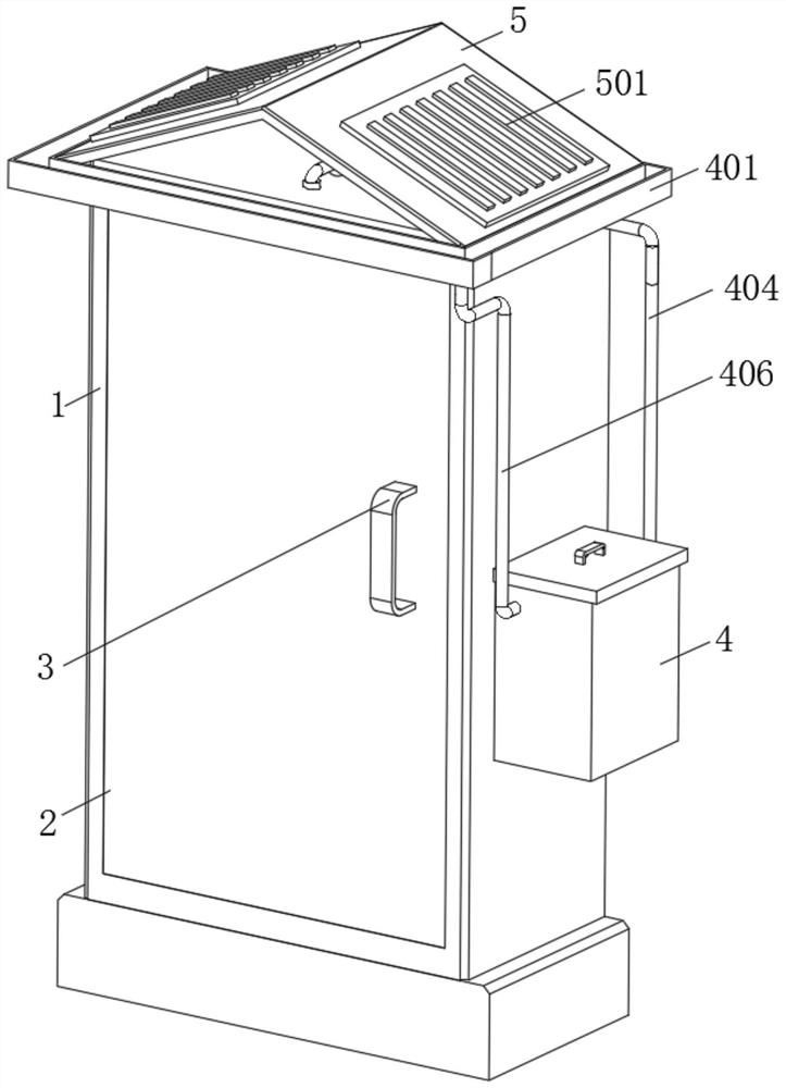
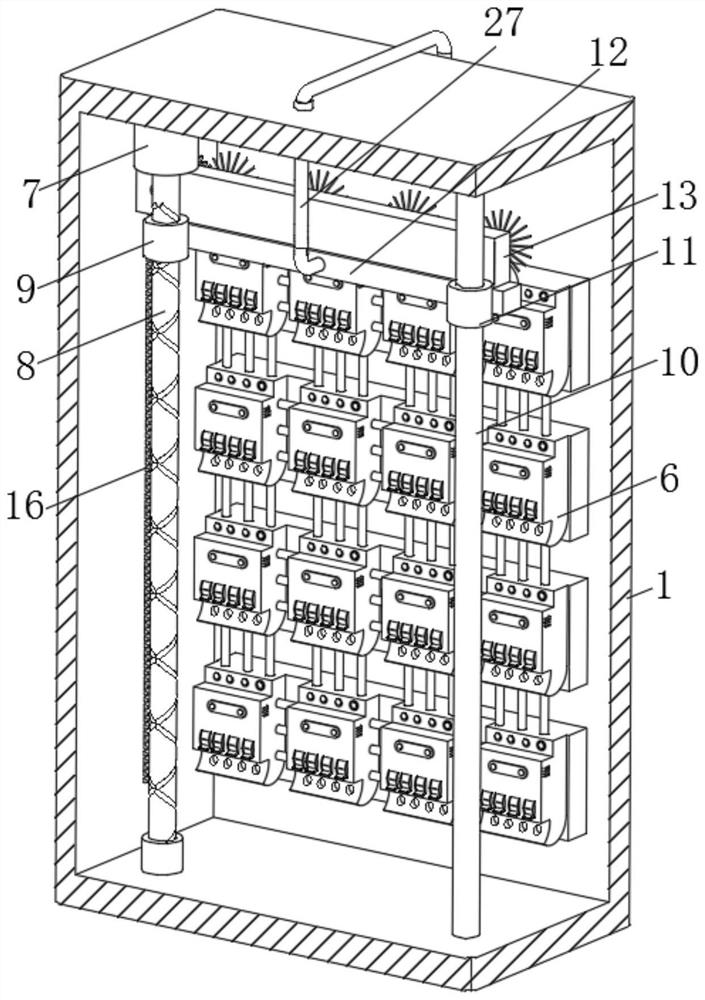
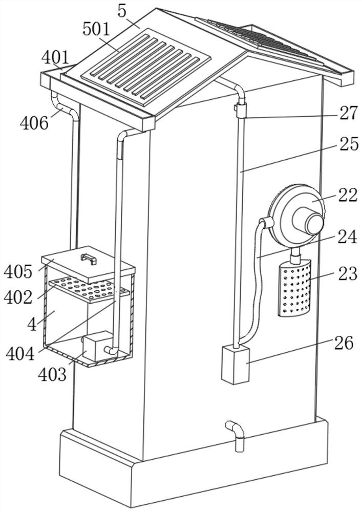
[0026] like Figure 1-6 As shown, an outdoor high and low voltage power distribution cabinet includes a power distribution cabinet body 1, the end face of the power distribution cabinet body 1 is hinged with a cabinet door 2 through hinges, and the inner side wall of the power distribution cabinet body 1 is fixedly installed with a number of Electrical components 6, a motor 7 is fixedly installed on the inner upper wall of the power distribution cabinet body 1, the output end of the motor 7 is fixedly connected with a reciprocating screw rod 8, and the outer side wall of the reciprocating screw rod 8 is threadedly connected with a screw sleeve 9, the power distribution cabinet body A sliding rod 10 is fixedly connected between the inner upper wall and the bottom wall of 1, a sliding sleeve 11 is slidably connected to the outer side wall of the sliding rod 10, and an air guide box 12 is fixedly connected to the outer side wall of the screw sleeve 9 and the sliding sleeve 11 together. A dust suction fan 22 is fixedly installed on the end face of the electric cabinet body 1 away from the cabinet door 2, the air outlet pipe on the dust suction fan 22 is threadedly connected with a filter bag 23, and the air inlet pipe on the dust suction fan 22 is fixedly connected with a connecting pipe 24, which is connected to One end of the pipe 24 is fixedly connected with a dust suction pipe 25 , one end of the connecting pipe 24 is fixedly connected with a counterweight 26 , and the other end of the dust suction pipe 25 extends through the outer wall of the power distribution cabinet body 1 to the inside thereof and is connected with the air guide box 12 . Fixed connection, the end face of the air guide box 12 is fixedly connected with a number of dust suction hoods 33, the upper surface of the air guide box 12 is fixedly connected with the equipment box 13, and the inner side wall of the equipment box 13 is rotatably connected with the connecting shaft 14 through the bearing. One end of the shaft 14 extends through the inner wall of the equipment box 13 to the outside thereof and is fixedly connected with a gear 15. The inner side wall of the power distribution cabinet body 1 is fixedly connected with a number of teeth 16, and the outer surface of the gear 15 meshes with the teeth 16 , the outer side wall of the connecting shaft 14 is fixedly connected with the first sprocket 17, the inner side wall of the equipment box 13 is rotatably connected with several transmission shafts 18 through bearings, and one end of the several transmission shafts 18 extends through the inner wall of the equipment box 13 to A cleaning brush 19 is fixedly connected to the outside thereof, the outer side walls of several transmission shafts 18 are fixedly connected with second sprockets 20, and the outer surfaces of the first sprocket 17 and several second sprockets 20 are jointly connected with a chain 21. , the outer side wall of the cabinet door 2 is fixedly connected with the handle 3, and the counterweight 26 can pull out the dust suction pipe 25, so as to prevent the dust suction pipe 25 from affecting the maintenance of the staff.
[0027] Several dust hoods 33 and cleaning brushes 19 are located in front of several electrical components 6, which is beneficial and improves the cleaning quality.
[0028] The power distribution cabinet body 1, the end face and the upper surface are fixedly connected to the limit sleeve 27, and the two limit sleeves 27 are both sleeved on the outer side wall of the dust suction pipe 25, which can limit the position of the dust suction pipe 25 and avoid its jamming. live.
[0029]A top plate 5 is fixedly connected to the upper surface of the power distribution cabinet body 1, and a water storage tank 4 and a guide box 401 are fixedly connected to the outer side walls of the power distribution cabinet body 1 respectively. The guide box 401 is located below the top plate 5, and the guide box 401 A water inlet pipe 406 is fixedly connected between the bottom end of the water tank 4 and the water storage tank 4, a water pump 403 is fixedly connected to the inner bottom wall of the water storage tank 4, and a guide pipe 404 is fixedly connected to the output pipe of the water pump 403. The end face is provided with a partition layer 28, the inner side wall of the partition layer 28 is fixedly connected with heat dissipation fins 29, the end surface of the heat dissipation fin 29 is fixedly connected with a guide plate 30, and a number of guide holes 31 are opened on the guide plate 30, One end of the guide pipe 404 penetrates the outer side wall of the distribution cabinet body 1 and extends to the interior of the partition 28 . The interior of the partition 28 is fixedly connected with a water outlet pipe 32 , and one end of the water outlet pipe 32 penetrates the inner wall of the distribution cabinet body 1 and extends to the outside thereof. , the deflector 30 is an inclined structure, and the upper surface of the water storage tank 4 is clamped with a cover plate 405 to utilize rainwater, which is beneficial and saves water resources.
[0030] A filter screen 402 is fixedly connected to the inside of the water storage tank 4, which can filter the impurities in the rainwater, so as to avoid the blockage of the diversion hole 31 and affect the flow of water.
[0031] A solar photovoltaic panel 501 is fixedly connected to the upper surface of the top plate 5. The solar photovoltaic panel 501 is electrically connected to the dust suction fan 22, the water pump 403 and the motor 7 respectively, which can absorb solar energy, which is beneficial to saving and environmental protection.
[0032] It should be noted that the present invention is an outdoor high and low voltage power distribution cabinet. The staff first checks the equipment, and then installs the equipment in a suitable position outdoors. When there is too much dust in the power distribution cabinet body 1, vacuum The fan 22 starts to use the connecting pipe 24 to draw air through the dust suction pipe 25, and then vacuums the surface of the electrical component 6 through the dust suction hood 33 on the air guide box 12. The motor 7 starts to drive the reciprocating screw 8 to rotate, and the screw The sleeve 9 and the sliding rod 10 drive the air guide box 12 to move up and down, so that the gear 15 rolls on the teeth 16, drives the connecting shaft 14 to rotate, and then drives the first sprocket 17 to rotate, and drives several second sprockets through the chain 21. 20 is rotated, so that the cleaning brush 19 on the transmission shaft 18 is rotated, and the electrical components 6 are cleaned by the cleaning brush 19, and then the dust suction hood 33 absorbs the cleaned dust, and then transports it into the filter on the dust suction fan 22. In the bag 23, after the dust removal is completed, the motor 7 continues to rotate so that the air guide box 12 is reset, the counterweight 26 uses its own gravity to pull out the dust suction pipe 25, and the staff removes the filter bag 23, and then cleans it. When it rains, the rainwater flows into the guide box 401, and then the water is transported into the water storage tank 4 through the water inlet pipe 406, and then the water is transported into the partition 28 through the water pump 403. Then the water flows through the guide holes 31 on the guide plate 30, absorbs the heat on the heat dissipation fins 29, and then discharges through the water outlet pipe 32. When the water storage tank 4 is short of water, the staff will cover the The plate 405 is opened, and then the tap water can be poured into the water storage tank 4 .
[0033] The basic principles and main features of the present invention and the advantages of the present invention have been shown and described above. Those skilled in the art should understand that the present invention is not limited by the above-mentioned embodiments. The above-mentioned embodiments and descriptions only illustrate the principle of the present invention. Without departing from the spirit and scope of the present invention, the present invention will also have Various changes and modifications fall within the scope of the claimed invention. The claimed scope of the present invention is defined by the appended claims and their equivalents.

PUM

no PUM

Description & Claims & Application Information

We can also present the details of the Description, Claims and Application information to help users get a comprehensive understanding of the technical details of the patent, such as background art, summary of invention, brief description of drawings, description of embodiments, and other original content. On the other hand, users can also determine the specific scope of protection of the technology through the list of claims; as well as understand the changes in the life cycle of the technology with the presentation of the patent timeline. Login to view more.

Similar technology patents

Classification and recommendation of technical efficacy words

  • Extended service life
  • Guaranteed performance

Preparing method for 6-series aluminum alloy sectional bar

InactiveCN105838938APrecise control of heating temperatureGuaranteed performanceAluminium alloyArtificial aging
Owner:广西南南铝加工有限公司
Why Eureka
Try Eureka