Sander feeding device with positioning guide function

A feeding device, positioning and guiding technology, applied in grinding/polishing safety devices, machine tools suitable for grinding workpiece planes, manufacturing tools, etc., can solve problems such as affecting service life, large impact force, and prone to tilting, etc. Achieve the effects of increasing service life, eliminating impact force and fast positioning

Inactive Publication Date: 2020-11-20
盐城鼎恒机械有限公司
View PDF12 Cites 0 Cited by
  • Summary
  • Abstract
  • Description
  • Claims
  • Application Information

AI Technical Summary

Problems solved by technology

A conveniently adjustable sander feeding device in the above-mentioned patent has the following disadvantages: when the wood slides from the feed plate to the blanking plate, it is easy to tilt, and it will impact the blanking plate during the sliding process. Depending on the roughness and quality of the blanking plate, the impact force of the blanking plate is variable, but only one end of the blanking plate is welded on the feed frame, which has no buffering effect. The long-term impact of the blanking plate will seriously affect its use. Life, so there is too much impact force in the feeding process, which affects the service life of the overall device

Method used

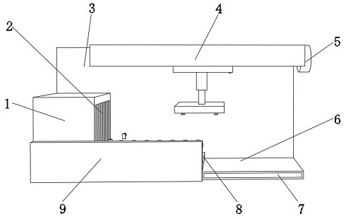
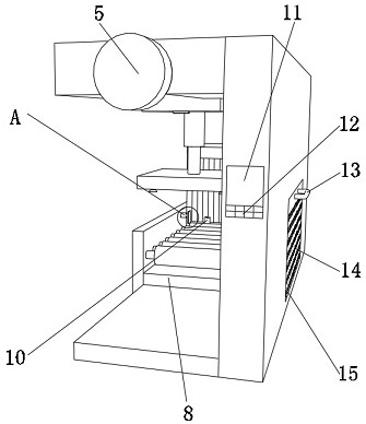
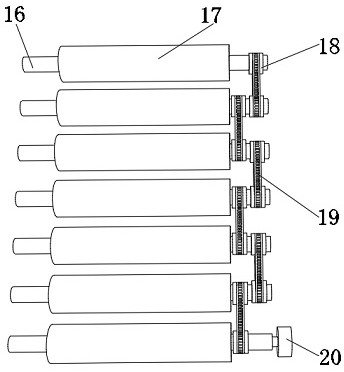

Image

  • Sander feeding device with positioning guide function
  • Sander feeding device with positioning guide function
  • Sander feeding device with positioning guide function

Examples


Embodiment Construction

[0029] The technical solution of this patent will be further described in detail below in conjunction with specific embodiments.

[0030] Embodiments of the present patent are described in detail below, examples of which are shown in the drawings, wherein the same or similar reference numerals designate the same or similar elements or elements having the same or similar functions throughout. The embodiments described below by referring to the figures are exemplary and are only used for explaining the patent, and should not be construed as limiting the patent.

[0031] In the description of this patent, it is to be understood that the terms "center", "upper", "lower", "front", "rear", "left", "right", "vertical", "horizontal", The orientation or positional relationship indicated by "top", "bottom", "inner", "outer", etc. is based on the orientation or positional relationship shown in the drawings, and is only for the convenience of describing this patent and simplifying the des...


PUM


Abstract

The invention discloses a sander feeding device with a positioning guide function, and relates to the technical field of sander feeding. In order to solve the problem of overlarge impact force duringfeeding, the sander feeding device specifically comprises a fixing bottom plate, the outer wall of one side of the fixing bottom plate is provided with a fixing plate, the outer wall of one side of the fixing plate is provided with a top plate, the outer wall of one side of the top plate is provided with a sliding groove, and a transmission mechanism is arranged in the sliding groove. According tothe sander feeding device, by arranging the transmission mechanism, a first motor is started and drives a threaded rod to move, then a sliding block is driven to move, the height between the slidingblock and a wood board is measured through a first infrared sensor on the sliding block, then the required lifting distance of a first electric hydraulic rod can be determined, the effect of rapidly positioning the height of the wood board is achieved, and damage caused to electric suction cups in the process of seeking the position of the wood board is prevented; and meanwhile, by using the electric suction cups to suck and release the wood board, impact force caused when the wood board falls is eliminated, and the service life of the whole device is prolonged.

Description

technical field [0001] The invention relates to the technical field of sander feeding, in particular to a sander feeding device with a positioning and guiding function. Background technique [0002] Sanding is a process that makes the surface of the board smooth while increasing the surface strength and uniform thickness. In traditional sanding, the board needs to be transported manually, which has potential safety hazards. And when the board is transported to the sander, the board must be manually cleaned. Positioning, if the positioning is inaccurate, the wood board after sanding will not meet the demand, so a sander feeding device with positioning and guiding functions is needed. [0003] After retrieval, the Chinese patent application number is CN209021883U, which discloses a conveniently adjustable sander feeding device, including a workbench and a feeder device, the feeder device is fixedly installed on one end of the workbench, and the working A sanding frame is fixe...

Claims


Application Information

Patent Timeline
Patent Type & Authority Applications(China)
IPC IPC(8): B24B7/28B24B41/00B24B41/02B24B49/12B24B55/00B24B41/06
CPCB24B7/28B24B41/005B24B41/007B24B41/02B24B41/06B24B49/12B24B55/00
Inventor 李青祝马玉娟李清华张培培
Owner 盐城鼎恒机械有限公司
Why Eureka
Try Eureka