Hydraulic drive type foot type bionic humanoid robot

A humanoid robot, driven technology, applied in the direction of motor vehicles, transportation and packaging, etc., can solve the problem that the number of degrees of freedom of the leg mechanism cannot meet high flexibility and high obstacle avoidance ability, restrict the walking ability and engineering application of biped robots, Problems such as motion accuracy and response speed are limited, to achieve the effect of high power-to-weight ratio, strong load capacity, and reduced volume

Active Publication Date: 2020-11-20
YANSHAN UNIV
View PDF8 Cites 3 Cited by
  • Summary
  • Abstract
  • Description
  • Claims
  • Application Information

AI Technical Summary

Problems solved by technology

[0003] In addition, the current biped robot mainly adopts the motor drive mode, and the arrangement of the components of the leg mechanism is relatively scattered. The degree of freedom of the leg mechanism cannot meet the needs of high flexibility and high obstacle avoidance ability, which restricts the walking ability and Engineering application
Moreover, the biped machine is bulky in shape and cannot adapt to complex and changeable working environments. At the same time, it has low power-to-weight ratio, low working stability, small machine output, insufficient load capacity, poor dynamic characteristics, large leg joint mass, and limited range of motion. Defects such as small size, limited motion accuracy and response speed
Based on this, a hydraulic drive type with higher leg structure flexibility, stronger obstacle avoidance ability, higher integrated power-to-weight ratio, stable operation, small reversing impact, fast response, large thrust and strong load capacity was designed. Foot type bionic humanoid robot and its hydraulic control system are a problem to be solved urgently in the present invention

Method used


Image

  • Hydraulic drive type foot type bionic humanoid robot
  • Hydraulic drive type foot type bionic humanoid robot
  • Hydraulic drive type foot type bionic humanoid robot

Examples


Embodiment 1

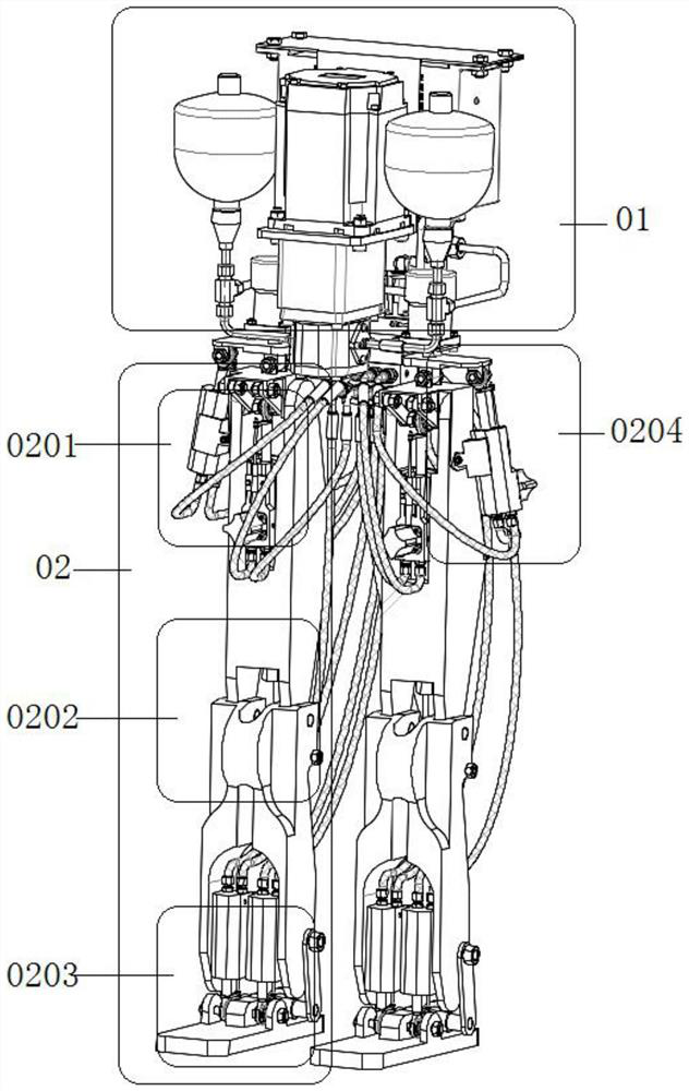
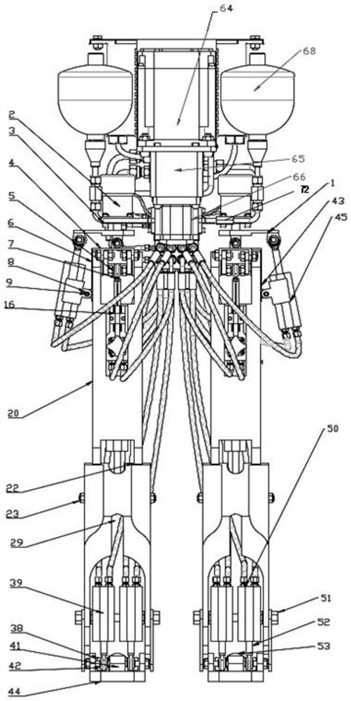
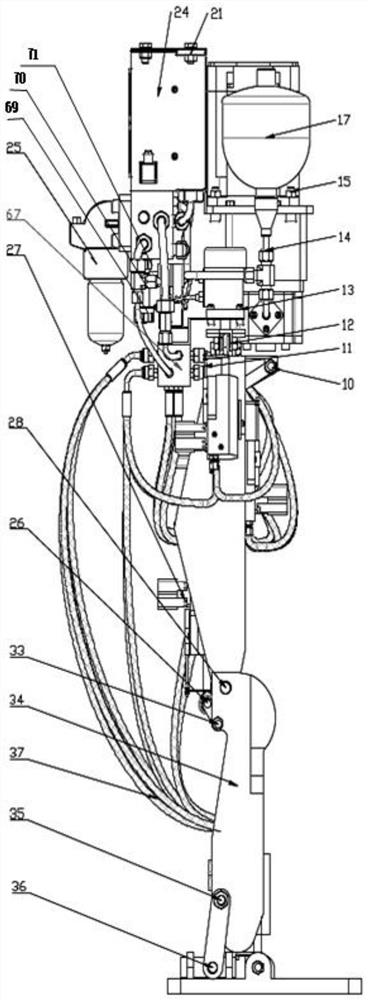
[0033] like Figure 1-4 As shown, this embodiment provides a hydraulically driven footed bionic humanoid robot, which mainly includes a hydraulic pump station 01, a leg mechanical structure 02, a hip joint 0201, a knee joint 0202, an ankle joint 0203, and a hydraulic drive unit 0204; The station 01 is fixed on the upper limb connecting frame 1 through the connecting parts, and the mechanical structure of the leg 02 is mainly divided into three joints according to the principle of human bionics. The hip joint 0201 has three degrees of freedom, which can realize the rotation, side swing and pitching of the leg structure. The hydraulic swing rod 2 rotates to drive the rotation of the hip joint 0201. The linear motion in the servo cylinder 55 drives the side swing and pitch motion of the hip joint 0201; the knee joint 0202 has one degree of freedom, which can realize the pitching action of the lower leg, and the servo cylinder cylinder rod 60 in the hydraulic drive unit 0204 is co...


PUM


Abstract

The invention discloses a hydraulic drive type foot type bionic humanoid robot and relates to the field of fluid transmission and control innovation. The robot comprises leg mechanical structures andhydraulic systems; the leg mechanical structures are used for being installed on an upper limb connecting frame of the robot in pairs, and each leg mechanical structure comprises a hip joint, a thighplate, a knee joint, a shank plate, an ankle joint and a foot plate which are sequentially connected from top to bottom; under the control of the hydraulic systems, the hip joints can achieve rotation, side swing and/or pitching actions, the knee joints can achieve pitching actions, and the ankle joints can achieve front-back pitching and/or left-right side swing actions. The robot is higher in movement flexibility, higher in obstacle avoidance capacity, higher in whole machine integration power-to-weight ratio, stable in work, small in reversing impact, quick in response, large in thrust andhigher in load capacity, overall components of the pump station system are vertically and integrally installed and arranged, the size of a robot pump station is effectively reduced, connecting pipes are conveniently connected with an oil way of a lower limb mechanism, and practicability is higher.

Description

technical field [0001] The invention relates to the innovative field of fluid transmission and control, in particular to a hydraulically driven footed bionic humanoid robot. Background technique [0002] With the rapid development of science and technology in the 21st century, informatization and mechanical automation have become the mainstream of development in the world today. In this context, robot technology has developed rapidly. Robots can be divided into wheeled robots and footed bionic robots according to their movement methods. Among them, footed bionic robots are popular because they can adapt well to unstructured environments and have high flexibility in their legs. Footed bionic robots can be divided into two-legged, four-legged, six-legged and multi-legged according to the number of feet. Among them, bipedal bionic humanoid robots are used in disaster relief, daily handling, scientific research and education, social security, catering services, It has the wides...

Claims


Application Information

Patent Timeline
Patent Type & Authority Applications(China)
IPC IPC(8): B62D57/032
CPCB62D57/032
Inventor 孔祥东黄智鹏杨建奎康岩付康平徐悦鹏郭建滨俞滨
Owner YANSHAN UNIV
Why Eureka
Try Eureka