Non-orbiting scroll assemblies, scroll compressors and refrigeration equipment
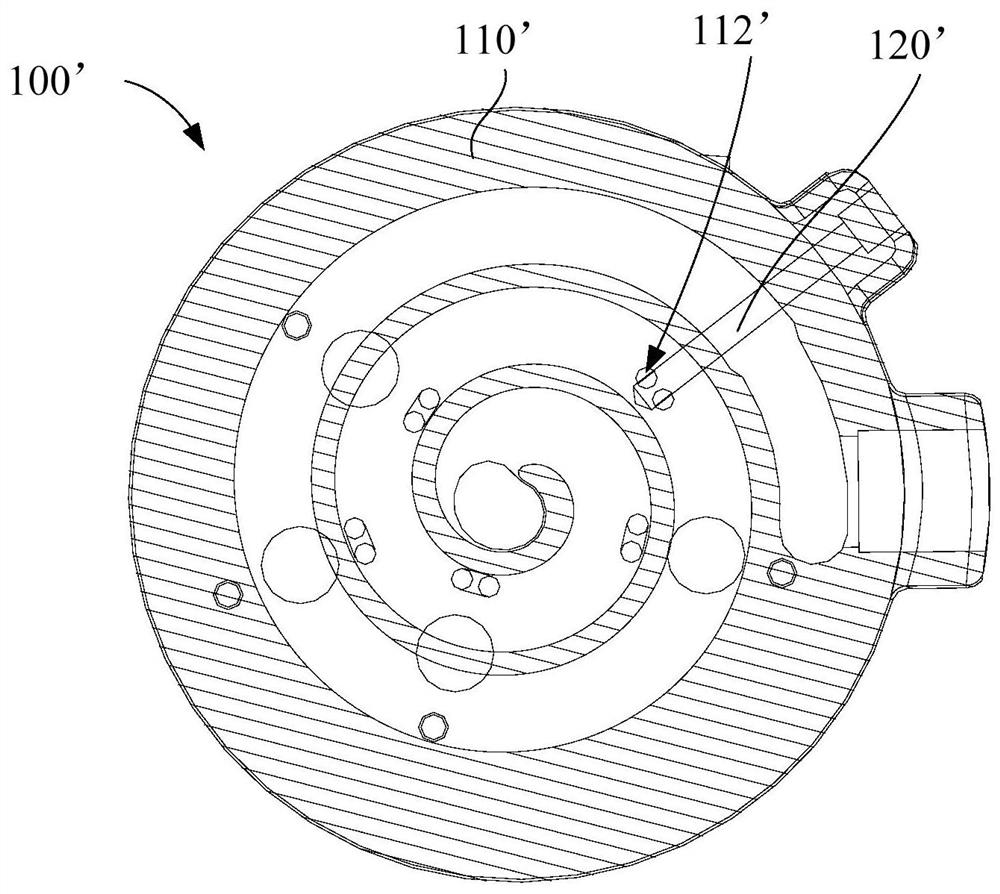
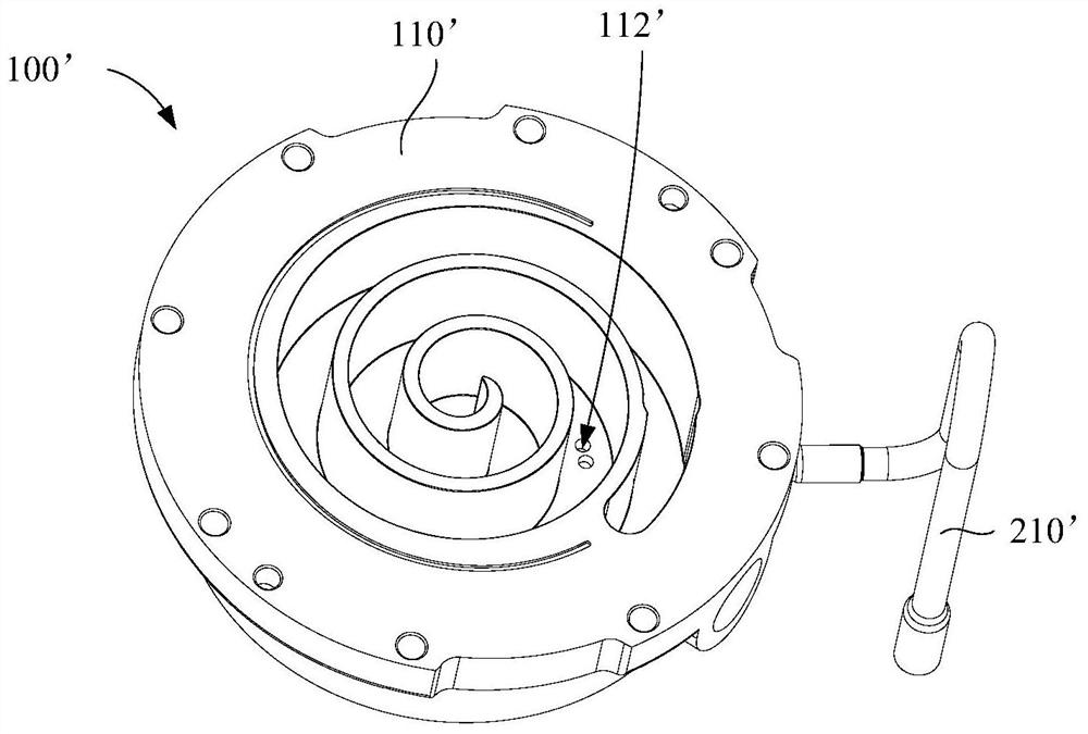
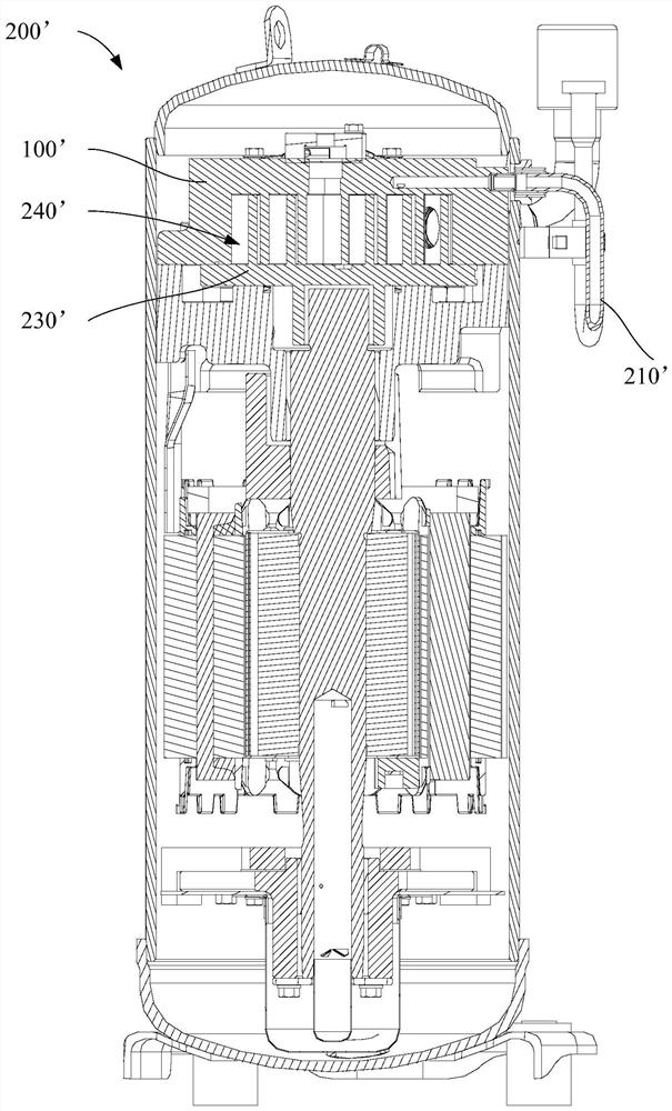
A scroll compressor and stationary scroll technology, applied in the field of compressors, can solve the problems of backflow, affecting the reliability of the scroll compressor 200', strong vibration of the enthalpy increasing pipeline 210' and the throttle valve plate, etc.
- Summary
- Abstract
- Description
- Claims
- Application Information
AI Technical Summary
Problems solved by technology
Method used
Image
Examples
Embodiment 1
[0063] Such as Figure 4 , Figure 5 with Image 6As shown, the embodiment of the first aspect of the present invention provides a fixed scroll assembly 100. The fixed scroll assembly 100 includes a disk body 110, an enthalpy increasing channel 120 and an enthalpy increasing nozzle 112, wherein the enthalpy increasing nozzle 112 and the enthalpy increasing nozzle 112 The enthalpy-increasing channel 120 is arranged on the disc body 110, and the enthalpy-increasing channel 120 is used to communicate with the enthalpy-increasing pipeline 210 of the scroll compressor 200, and the enthalpy-increasing nozzle 112 communicates with the compression channel 111 and the enthalpy-increasing channel 120, and the enthalpy-increasing channel 120 can Refrigerant gas is introduced from the refrigeration system into the compression chamber 240 of the scroll compressor 200 through the enthalpy-increasing pipeline 210 to realize the function of increasing enthalpy by gas injection. The gas volu...
Embodiment 2
[0069] On the basis of the first embodiment above, the second embodiment provides a fixed scroll assembly 100, wherein, as Figure 4 , Figure 5 with Image 6 As shown, the fixed scroll assembly 100 also includes: suction port 114, which is arranged on the disk body 110; on the cross section of the disk body 110, the line connecting the center of the suction port 114 and the center of the disk body 110 is the first A connecting line M, the connecting line between the side of the enthalpy-increasing nozzle 112 away from the first connecting line M and the center of the disk body 110 is the second connecting line N, the angle between the first connecting line M and the second connecting line N α ranges from -60° to 50°. That is, on the cross-section of the disk body 110 , the arrangement position of the enthalpy increasing nozzle 112 relative to the suction port 114 is specifically defined. Wherein, the disk body 110 is provided with an air suction port 114, and the air sucti...
Embodiment 3
[0073] On the basis of Embodiment 1 or Embodiment 2 above, Embodiment 3 provides a fixed scroll assembly 100, wherein, as Figure 4 , Figure 5 with Image 6 As shown, the fixed scroll assembly 100 also includes: a groove 116 arranged on the disk body 110; a worm gear 118 arranged in the groove 116, the worm gear 118 is in a spiral shape, and the groove of the worm gear 118 and the groove 116 A compression channel 111 is formed around the bottom, and an enthalpy increasing nozzle 112 is arranged in the compression channel 111 .
[0074] In this embodiment, the arrangement position of the enthalpy increasing nozzle 112 relative to the spiral tooth 118 is specifically limited. Wherein, a groove 116 and a worm gear 118 are arranged on the disc body 110, the worm gear 118 is helical and located in the groove 116, the worm gear 118 and the groove bottom of the groove 116 form a compression channel 111, and the enthalpy-increasing nozzle 112 is arranged in the compression channel...
PUM
 Abstract
Description
Claims
Application Information
 - R&D
- Intellectual Property
- Life Sciences
- Materials
- Tech Scout
- Unparalleled Data Quality
- Higher Quality Content
- 60% Fewer Hallucinations
Browse by: Latest US Patents, China's latest patents, Technical Efficacy Thesaurus, Application Domain, Technology Topic, Popular Technical Reports.
© 2025 PatSnap. All rights reserved.Legal|Privacy policy|Modern Slavery Act Transparency Statement|Sitemap|About US| Contact US: help@patsnap.com


