Smoke dust self-removal type boiler tail gas emission pipeline

A tail gas emission and boiler technology, which is applied in the direction of exhaust gas exhaust device, removal of solid residue, treatment of combustion products, etc., can solve the problems of power consumption of components, reduction of smoke exhaust from exhaust pipes, and reduction of boiler combustion efficiency, etc., so as to save electric energy The effect of reducing consumption, increasing emission efficiency, and improving boiler combustion efficiency

Inactive Publication Date: 2020-11-20
张舜
View PDF0 Cites 2 Cited by
  • Summary
  • Abstract
  • Description
  • Claims
  • Application Information

AI Technical Summary

Problems solved by technology

However, this treatment method requires the installation of complex and expensive electrical equipment to process the exhaust gas, and the components consume electric energy. What's more serious is that during the long-term discharge process, the smoke and dust in the exhaust gas are easy to accumulate in the exhaust pipe, resulting in a large amount of smoke exhausted by the exhaust pipe. Greatly reduce and affect the exhaust emission efficiency, thereby reducing the combustion efficiency of the boiler

Method used


Image

  • Smoke dust self-removal type boiler tail gas emission pipeline
  • Smoke dust self-removal type boiler tail gas emission pipeline
  • Smoke dust self-removal type boiler tail gas emission pipeline

Examples


Embodiment 1

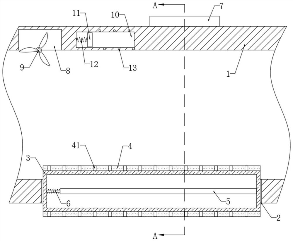
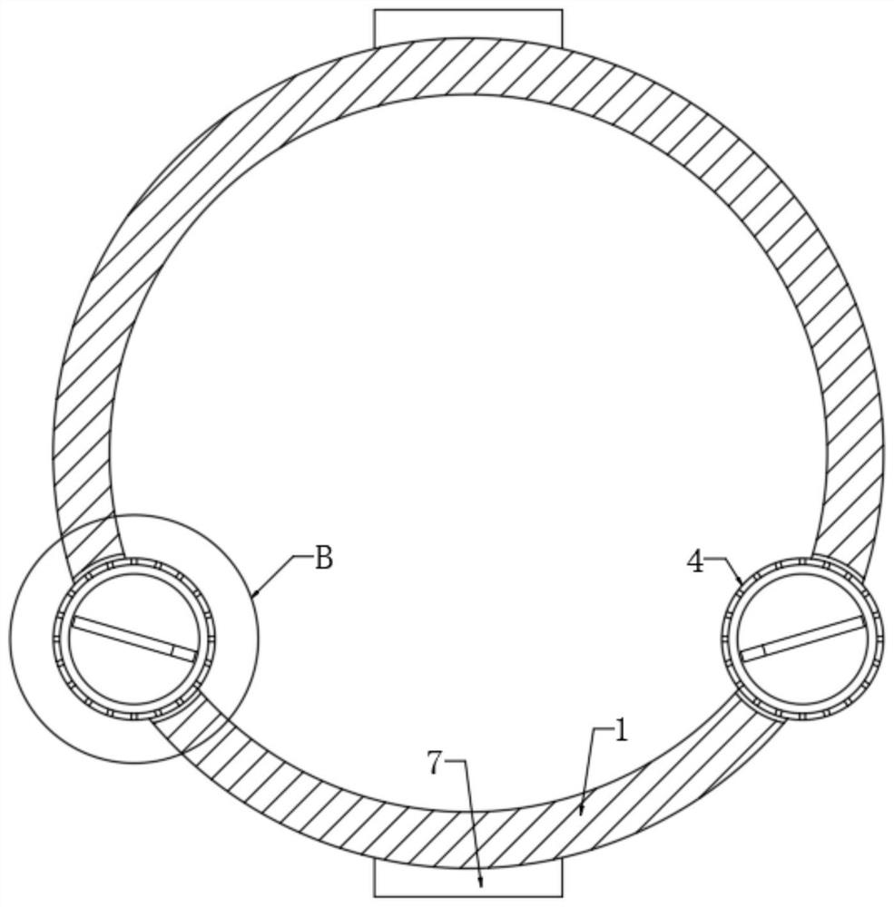
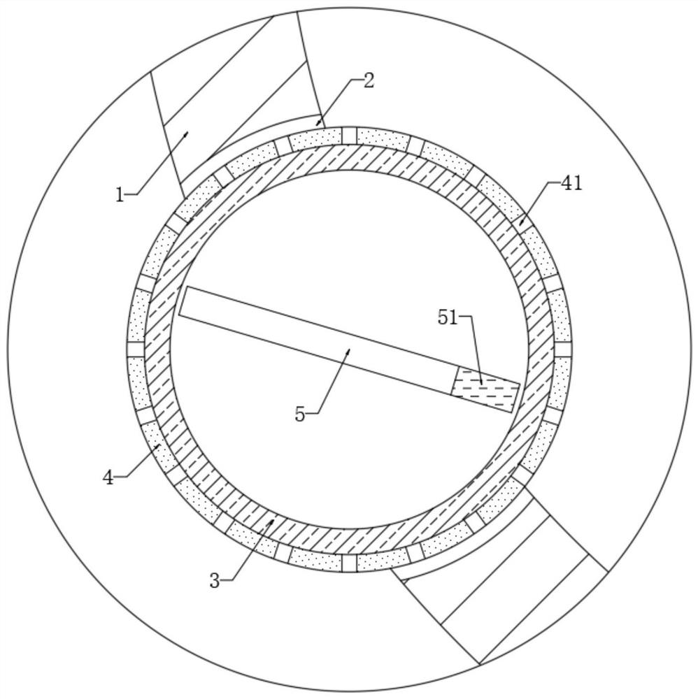
[0024] refer to Figure 1-3 , a self-cleaning soot type boiler tail gas discharge pipe, comprising an exhaust pipe 1, characterized in that the side wall of the exhaust pipe 1 is provided with an arc-shaped groove 2, and a glass cylinder 3 is fixedly connected in the arc-shaped groove 2, and the glass cylinder 3 is provided with a silicon steel sheet 5, and the side wall of the silicon steel sheet 5 is provided with a silk layer 51. And the silicon steel sheet 5 is rotatably connected in the glass cylinder 3 through the spring shaft 6, the glass cylinder 3 is covered with a cylinder 4, and the cylinder 4 is rotatably connected on the inner wall of the arc groove 2, and the side wall of the cylinder 4 is provided with a plurality of Through hole 41 .

[0025] It should be noted that, if image 3 As shown, the silk layer 51 is only arranged on the side wall of the part of the silicon steel sheet 5 close to the exhaust pipe 1, so that it can be guaranteed that static electricit...

Embodiment 2

[0033] refer to Figure 4-6 , different from Embodiment 1, the glass cylinder 3 is embedded with a rubber gas cover 14, and the inner bottom of the glass cylinder 3 is provided with a plurality of unidirectional air outlet holes 15, and the positions of each unidirectional air outlet hole 15 and the through hole 41 In one-to-one correspondence, the side wall of the glass cylinder 3 is fixedly connected with a one-way air inlet pipe 16 communicating with the inside thereof.

[0034] It should be noted that the one-way air outlet 15 only allows air to be discharged from the rubber air cover 14 to the outside of the glass cylinder 3 , and the one-way air inlet pipe 16 only allows air to flow in from the outside of the glass cylinder 3 into the rubber air cover 14 . Specifically, when manufacturing, it is only necessary to install a one-way valve in the air outlet or the air intake pipe. Further, such as Image 6 As shown, the one-way air outlet hole 15 is only arranged on the p...


PUM


Abstract

The invention discloses a smoke dust self-removal type boiler tail gas emission pipeline. The smoke dust self-removal type boiler tail gas emission pipeline comprises a gas exhaust tube, wherein an arc-shaped slot is formed in the side wall of the gas exhaust tube; a glass tube is fixedly connected in the arc-shaped slot; a silicon steel piece is arranged in the glass tube; the side wall of the silicon steel piece is equipped with a silk layer; the silicon steel piece is rotatably connected in the glass tube through a spring shaft; a cylinder sleeves outside the glass tube; the cylinder is rotatably connected onto the inner wall of the arc-shaped slot; a plurality of through holes are formed in the side wall of the cylinder; and two electromagnets are fixedly connected on the side walls ofthe gas exhaust tube. The silicon steel piece swings back and forth in the glass tube, and the silk layer on the side wall of the silicon steel piece rubs with the glass tube continuously, so that static electricity can be generated on the surface of the glass tube, smoke gas in flowing tail gas in the exhaust tube can be adsorbed, smoke dust does not need to remove with special tail gas dust-removal equipment; and moreover, smoke dust accumulation is not generated in the gas exhaust tube, so that tail gas emission efficiency and boiler combustion efficiency of the gas exhaust tube are improved.

Description

technical field [0001] The invention relates to the relevant technical field of boiler tail gas pipelines, in particular to a self-cleaning smoke and dust type boiler tail gas discharge pipeline. Background technique [0002] When the boiler exhaust gas is discharged, it is necessary to remove the smoke and dust in the exhaust gas before it can be discharged into the air to prevent air pollution. [0003] Therefore, when the existing boiler tail gas is discharged, the tail gas discharge pipe is often used to transport the boiler position to other dust removal equipment such as a bag filter for dust removal treatment of the tail gas. However, this treatment method requires the installation of complex and expensive power equipment to process the exhaust gas, and the components consume electric energy. What's more serious is that during the long-term discharge process, the smoke and dust in the exhaust gas tend to accumulate in the exhaust pipe, resulting in a large amount of s...

Claims


Application Information

Patent Timeline
Patent Type & Authority Applications(China)
IPC IPC(8): F23J11/00F23J13/00F23J3/02F23J15/02
CPCF23J3/02F23J11/00F23J13/00F23J15/022F23J2217/101F23J2217/102
Inventor 张舜
Owner 张舜
Why Eureka
Try Eureka