Optical fiber axial nondestructive on-line detection device and method

A detection device and detection method technology, applied in the direction of measuring devices, optical instrument testing, testing optical fiber/optical waveguide equipment, etc., can solve the problems of weak back-diffraction light intensity, high device precision requirements, weak anti-interference ability, etc., to achieve Versatility, high precision, and quality-enhancing effects

Active Publication Date: 2020-11-20
JINAN UNIVERSITY
View PDF13 Cites 5 Cited by
  • Summary
  • Abstract
  • Description
  • Claims
  • Application Information

AI Technical Summary

Problems solved by technology

However, the shortcomings of this method are that the peak of the characteristic curve is selected as the axial azimuth of the polarization maintaining fiber, the accuracy is low, the axis fixing speed is slow, the anti-interference ability is weak, and the device accuracy is high.
This method is suitable for thicker optical fibers, but for ultra-fine optical fibers, the back-diffraction light intensity is weak, and it is greatly affected by external stray light, so it is not suitable for the fixed axis of ultra-fine optical fibers.
[0005] In addition, most of the reported special optical fiber positioning technologies and devices are only aimed at a specific special optical fiber, and are not universal. Axis technology and devices, making the related research and work based on special optical fiber axis technology faster, more efficient and more accurate

Method used


Image

  • Optical fiber axial nondestructive on-line detection device and method
  • Optical fiber axial nondestructive on-line detection device and method
  • Optical fiber axial nondestructive on-line detection device and method

Examples


Embodiment 1

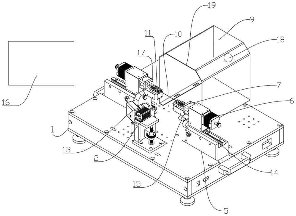
[0068] This embodiment provides an optical fiber axial non-destructive on-line detection device, through which the optical fiber axial non-destructive on-line detection is realized. Such as figure 1 As shown, the detection device of the present invention includes an image processing device 16 , an optical fiber clamp 11 , moving parts, rotating parts, an imaging screen 9 , a coherent light emitter 2 and an image recording device 13 , and the optical fiber clamp 11 is used to clamp the optical fiber 10 . The optical fiber 10 is an optical fiber from which the coating layer has been removed.

[0069] In a specific implementation process, the optical fiber clamp 11 , moving parts, rotating parts, imaging screen 9 , coherent light emitter 2 and image recording device 13 can be installed through the device platform 1 .

[0070] Install the moving parts on the device platform, the moving parts include two symmetrically arranged, each moving part includes a slide rail 5 and a slide bl...

Embodiment 2

[0086] The present invention also provides an optical fiber axial non-destructive online detection method, through the method of this embodiment to realize the optical fiber axial non-destructive online detection, the method is as follows:

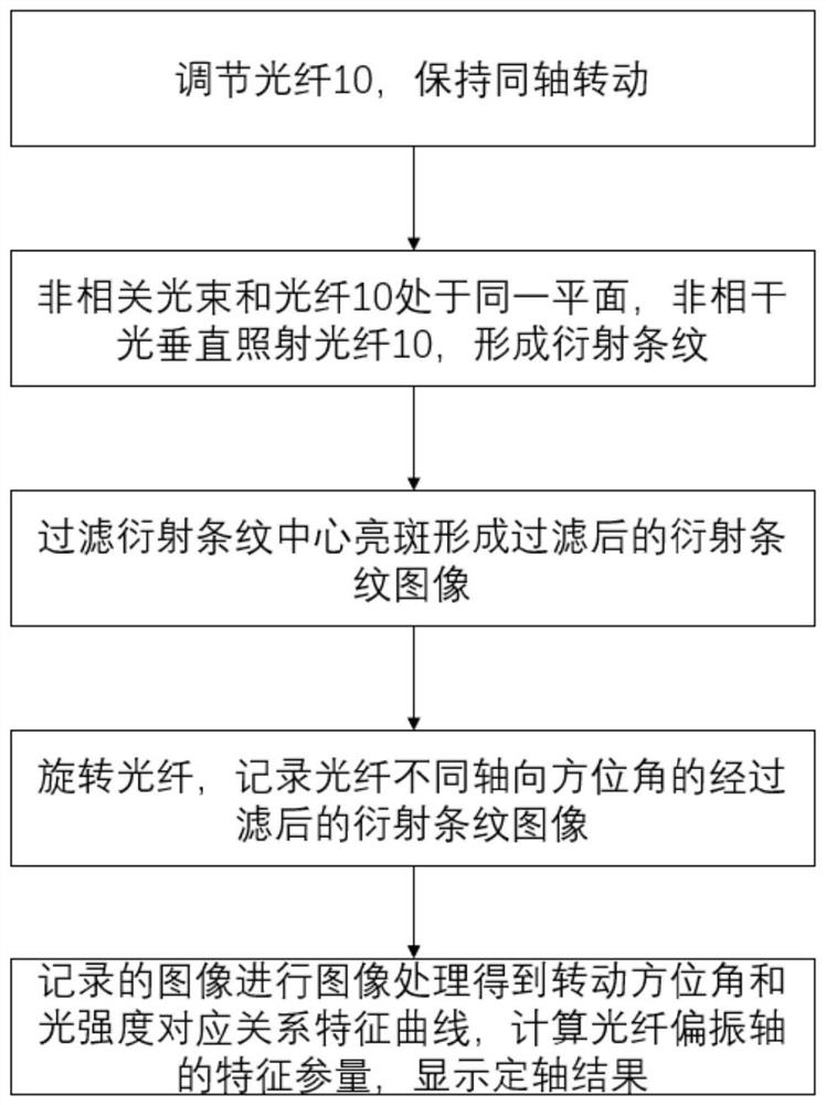
[0087] Such as figure 2 As shown, (1) Adjust the optical fiber 10 to keep it rotating coaxially. The coaxial rotation adjustment method is as follows: expose the tail end of one end of the optical fiber to a length of 0.5 cm to 1.0 cm, observe the operation of the tail end of the optical fiber as it rotates, and adjust to make the tail end There is no revolution at the end. Adjust the other end of the optical fiber 10 in the same way, and then keep the two ends of the optical fiber 10 at the same horizontal position;

[0088] (2) The coherent light beam and the optical fiber 10 are placed on the same plane, and the incoherent light irradiates the optical fiber 10 vertically to form diffraction fringes;

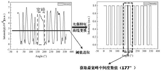
[0089] (3) Filter the central br...

Embodiment 3

[0100] This embodiment uses the device of the above-mentioned embodiment 1 to carry out the detection method of the embodiment 2, and the optical fiber 10 is selected as Figure 9 Shown is a 40-μm-diameter ultra-fine polarization-maintaining fiber with the coating removed.

[0101] The above detection methods are:

[0102] Clamp the two ends of the optical fiber 10 with the optical fiber clamp 11, and by adjusting the vertical adjustment device 7 and the horizontal adjustment device on the rotating part, the optical fiber clamps 11 at both ends are in the coaxial rotation state as much as possible; The adjustment on the surface can be observed with the aid of a microscope.

[0103] Rotate the adjustment rod 15 to push the slider 14, and use the pressure sensor to measure the tension on the optical fiber 10, and judge that the light is in a straight state according to the stable value of the tension; the adjustment rod 15 and the slider 14 are all high-precision adjustment str...


PUM

PropertyMeasurementUnit
diameteraaaaaaaaaa
diameteraaaaaaaaaa

Abstract

The invention provides an optical fiber axial nondestructive on-line detection device and method, which belong to the technical field of optical fiber device processing and manufacturing, and solve the problem that the fixed axis of a 40-micron ultra-small-diameter polarization maintaining optical fiber is simultaneously suitable for various special optical fibers. The device comprises an image processing device, a rotating part, an optical fiber clamp, an imaging screen, a coherent light emitter and an image recording device. The optical fiber clamp is installed on the rotating part and usedfor clamping an optical fiber, and the rotating part is used for driving the optical fiber to coaxially rotate through the optical fiber clamp. The coherent light emitter and the imaging screen are arranged on the two sides of the optical fiber clamp respectively, and light beams emitted by the coherent light emitter are used for vertically irradiating the optical fiber. A central bright spot filtering part is arranged on the imaging screen; and the image recording device is arranged on one side of the imaging screen towards the optical fiber clamp and is connected with the image processing device. The imaging screen is provided with the central bright spot filtering part, thereby reducing the impact on the imaging quality from the central bright spot, improving the imaging quality, and improving the fixed axis accuracy through the detection device.

Description

technical field [0001] The invention relates to the technical field of optical fiber device processing and manufacturing, and more particularly, to an optical fiber axial non-destructive on-line detection device and method. Background technique [0002] At present, the special optical fibers used in the world can be roughly divided into three categories, including: microstructured optical fibers, ordinary polarization-maintaining optical fibers and ultra-fine diameter polarization-maintaining optical fibers. Among them, the microstructured fiber is the most widely used photonic crystal fiber, usually composed of a single medium and the microstructured cladding is composed of air holes on the order of wavelength that are closely arranged in the two-dimensional direction and keep the structure unchanged in the axial direction. Photonic crystal fiber presents many characteristics that are difficult to realize in traditional fiber, so it has received extensive attention and has ...

Claims


Application Information

Patent Timeline
Patent Type & Authority Applications(China)
IPC IPC(8): G01M11/00
CPCG01M11/33
Inventor 陈哲余健辉湛元松吴朋军唐洁媛
Owner JINAN UNIVERSITY
Why Eureka
Try Eureka