
Unmanned road sweeper

A road sweeper and vehicle frame technology, which is applied in the field of sanitation, can solve problems such as affecting the driving of other vehicles, uncontrollable turning angles, and difficult control, so as to reduce the workload of sanitation workers, shorten response time, and improve response accuracy.

Inactive Publication Date: 2020-11-24
SHANGHAI DIANJI UNIV
View PDF5 Cites 1 Cited by
  • Summary
  • Abstract
  • Description
  • Claims
  • Application Information

AI Technical Summary

Problems solved by technology

[0003] Most of the existing road sweepers require sanitation workers to drive or control them, which cannot realize automated and intelligent operations, resulting in a waste of manpower and financial resources
The disc brush of the existing unmanned road sweeper is seriously worn; if the road sweeper breaks down during work, it can only be taken back to the repair shop manually; the existing unmanned road sweeper has a complex structure and high cost. Road cleaning in urban residential areas, park road cleaning, etc. in places such as parks is not applicable
The most important thing is that the existing unmanned road sweepers have problems such as safety and stability, and there are problems such as uncontrollable or difficult control of the turning angle, long adjustment time, etc., especially when the unmanned road sweeper is turning. It is prone to rollover, or the turning angle is uncontrollable and deviates from the route, which affects the driving of other vehicles

Method used


Image

  • Unmanned road sweeper
  • Unmanned road sweeper
  • Unmanned road sweeper

Examples


Embodiment Construction

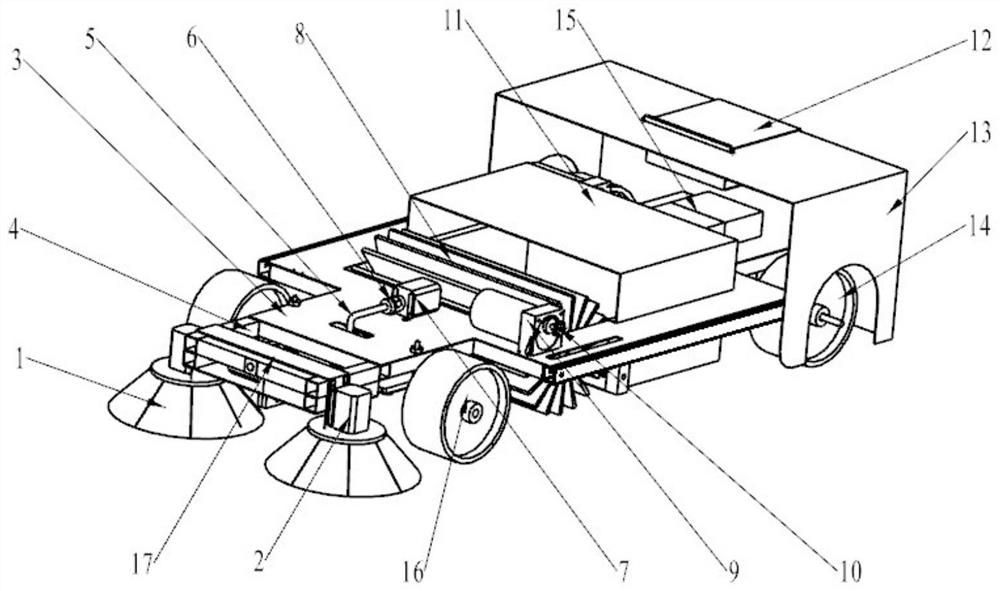
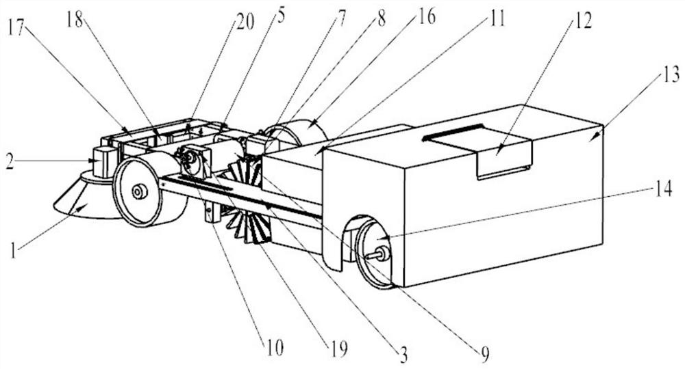
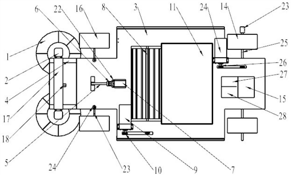
[0023] Such as Figures 1 to 8 As shown, the embodiment of the present invention provides an unmanned road sweeper. Next, the invention will be further described in terms of the body structure part and the steering part of the road sweeper.

[0024] The body structure part includes a power supply module, a remote control module, a cleaning module, a driving module and a steering module.

[0025] Such as Figures 1 to 3 As shown, the driving module includes a driving motor 24 and a rear axle 25 arranged on the vehicle frame. Drive motor 24 is installed on the rear side of road sweeper, and sprocket wheel 26 is housed on its output shaft, and sprocket wheel is also housed on rear wheel shaft 25, drives rear wheel shaft 25 to rotate by sprocket drive mechanism when drive motor 24 works by chain , thereby driving the rear wheels (14) installed at the two ends of the rear axle 25 to rotate, and the unmanned road sweeper begins to move forward. Lithium battery 15 provides power ...


PUM


Abstract

The invention discloses an unmanned road sweeper. The unmanned road sweeper comprises a power module, a driving module, a sweeping module, a remote control module and a drive-by-wire module. A core controller is combined with the power module, the remote control module, the driving module and the drive-by-wire module, so that rapid and stable driving of a vehicle is guaranteed, and a PID controller is designed, so that the speed response speed and precision of a small unmanned road sweeper body are improved, and the drive-by-wire module is combined with a sliding mode control algorithm, so that the response speed and precision of a corner signal of the small unmanned road sweeper body are improved, a safe and stable autonomous sweeping function is achieved, and a remote control module is designed, so that the road sweeper body is convenient to move when breaking down, and a lifting plate is designed to control the height of a plate brush to reduce plate brush loss. Therefore, the garbage sweeping efficiency is improved, the possible abrasion is reduced, the stability and the safety of the unmanned road sweeper in a driving process are improved, and the burden of sanitation workersis reduced.

Description

technical field [0001] The invention belongs to the field of sanitation, in particular to an unmanned road sweeper. Background technique [0002] The small unmanned road sweeper is a special vehicle for road garbage cleaning. It is widely used in urban streets, municipal squares, airport pavements, urban residential areas, parks and other road cleaning operations. Most of the existing unmanned road sweepers require sanitation workers to drive or control them, which cannot realize automated and intelligent operations, resulting in a waste of human and financial resources. The existing unmanned road sweeper can realize remote control of the start and stop of the car. It is a large vehicle. Multiple sensors are used to realize the unmanned sweeper to sense the surrounding obstacles and help the sweeper to safely avoid pedestrians, driving and various obstacles. . [0003] Most of the existing road sweepers require sanitation workers to drive or control them, which cannot rea...

Claims


Application Information

Patent Timeline
Patent Type & Authority Applications(China)
IPC IPC(8): E01H1/00E01H1/05B60K1/00B60B35/12B60L15/20B62D5/04
CPCB60B35/122B60K1/00B60L15/20B62D5/04E01H1/005E01H1/05Y02T10/64Y02T10/72
Inventor 仝光朱金栋尹浩周汉杰李解
Owner SHANGHAI DIANJI UNIV
Learn More