Trough type photo-thermal power generation system

A solar-thermal power generation and trough-type technology, applied in solar thermal power generation, solar heating systems, solar heat storage, etc., can solve the problems of heavy workload for operators, increased difficulty of manual cleaning, and reduced light concentration efficiency of solar thermal power generation systems, etc. problem, to reduce the probability of occurrence and shorten the time for downtime maintenance

Active Publication Date: 2020-11-24
胜利油田胜兴集团有限责任公司
View PDF6 Cites 1 Cited by
  • Summary
  • Abstract
  • Description
  • Claims
  • Application Information

AI Technical Summary

Problems solved by technology

Moreover, solar thermal power generation systems are generally deployed in areas with sufficient sunlight, flat terrain, and geological stability, such as Gobi, plains, etc. A large amount of dust or dust and other attachments will accumulate on the protection tube, which will greatly reduce the light concentration efficiency of the solar thermal power generation system. It is necessary to regularly clean the protection tube and other light concentration components. The existing cleaning methods usually use manual cleaning. , and because the length of the molten salt tube in the power generation system is relatively large, and because there are arc-shaped heat collecting plates and various supports under the protection tube, the manual cleaning process is cumbersome and the workload of the operator is huge. The molten salt tube and the heat collector plate still have a certain amount of heat radiation when they are shut down, which further increases the difficulty of manual cleaning. Therefore, how to realize the rapid and efficient cleaning of the protective tube is a major research problem for researchers at present.

Method used


Image

  • Trough type photo-thermal power generation system
  • Trough type photo-thermal power generation system
  • Trough type photo-thermal power generation system

Examples


Embodiment 1

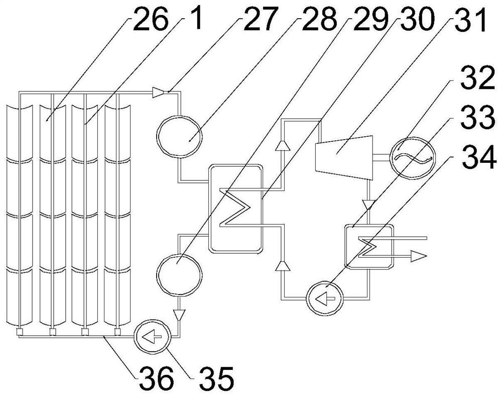
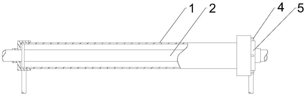
[0029] Such as Figure 1~6 As shown, the present embodiment includes multiple rows of heat collecting plates 26, each row of said heat collecting plates 26 is provided with a support rod, the support rod is provided with an annular joint 5, and the protective tube 1 runs through a plurality of joints 5, each A molten salt pipe 2 is provided inside a protection pipe 1, and one end of a plurality of molten salt pipes 2 communicates with a high-temperature pipeline 27, and the other end of a plurality of molten salt pipes 2 communicates with a low-temperature pipeline 37, which is characterized in that: Each of the protection tubes 1 is provided with a cleaning mechanism, and the high-temperature pipeline 27 is sequentially connected with the high-temperature storage tank 28, the liquid inlet of the heat exchanger 30, the liquid inlet of the steam turbine 31, and the generator 32. The pipeline 37 is sequentially connected with the liquid outlet of the cryogenic storage tank 29, t...

Embodiment 2

[0034] Such as Figure 2-6 As shown, in this embodiment, on the basis of Embodiment 1, baffle plates are provided on the two inner walls at both ends of the arc-shaped cavity, and baffle plates are provided on the two side walls of each follower plate 20. The pins 22, in the initial state, the follower plate 20 moves through the gap between the two baffles and then extends to the middle of the arc-shaped cavity, and the two pins 22 are respectively in contact with the inner side walls of the baffles. When the two movable plates 6 fully entered the arc cavity, the adjustment gear 19 and the rack 21 kept in contact all the time, so as to realize the spacing of the follower plate 20 and the movable plate 6, and when the movable plate 6 moved from the arc When moving out of the cavity, in order to prevent the movement of the other movable plate 6 from being hindered due to the excessive displacement of one of the movable plates 6, baffle plates are respectively provided on the two...

Embodiment 3

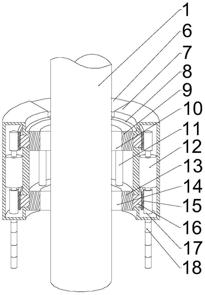
[0037] Such as Figure 2-6 As shown, in this embodiment, on the basis of Embodiment 1, arc-shaped grooves 8 are formed on both ends of the fixing plate 7 , and the arc-shaped grooves 8 match the joints 5 . When the housing is located at the beginning of the protective tube 1 or moved to the terminal of the protective tube 1, the electrical components in the housing are in an idle state, and the arc-shaped grooves 8 at both ends of the fixing plate 7 can be overlapped on the joint 5, and the arc-shaped concave There is a certain static friction force between the groove 8 and the outer wall of the joint 5. Compared with the case completely sleeved on the protection tube 1, the contact area between the whole device and the protection tube 1 and the joint 5 is larger, and the force is more balanced, avoiding the device Rotation occurs on the protection tube 1, and the speed of the driving motor and the bidirectional motor 12 is preset, and the components in a stable state can ensu...


PUM


Abstract

The invention discloses a trough type photo-thermal power generation system. The trough type photo-thermal power generation system comprises a plurality of rows of heat collecting plates, a supportingrod is arranged on each row of heat collecting plates, connectors are arranged on the supporting rods, protective pipes penetrate through the connectors, each protective pipe is provided with a cleaning mechanism, each cleaning mechanism comprises a shell, an arc-shaped cavity is formed in a fixing plate, the two ends of each arc-shaped cavity are open, two movable plates are arranged at the twoends of the arc-shaped cavity in a sliding mode, follow-up plates are arranged at the ends of the movable plates, a clamping plate I is arranged on the inner side wall of one flange, a clamping plateII is fixed to the inner side wall of the other flange, a cleaning assembly I is arranged on the inner side wall of the clamping plate I, and a cleaning assembly II is arranged on the inner side wallof the clamping plate II. According to the trough type photo-thermal power generation system, the tedious steps of traditional manual cleaning are omitted, the outer walls of the protective pipes on arow of heat collection plates are cleaned and dedusted at a time, the shutdown maintenance time of an existing photo-thermal power generation system is shortened, operators can be prevented from being exposed to the heat radiation environment for a long time, and the probability of safety accidents is reduced.

Description

technical field [0001] The invention relates to the field of new energy, in particular to a trough-type photothermal power generation system. Background technique [0002] Solar thermal power generation refers to the use of large-scale arrays of parabolic or dish-shaped mirrors to collect solar thermal energy, provide steam through heat exchange devices, and combine traditional steam turbines to drive motors to achieve the purpose of power generation. The use of solar thermal power generation technology avoids the expensive silicon crystal photoelectric conversion process, which can greatly reduce the cost of solar power generation; moreover, this form of solar energy utilization has an incomparable advantage over other forms of solar energy conversion, that is, the The heated water can be stored in a huge container, and it can still drive the steam turbine to generate electricity a few hours after the sun goes down, which means extending the time of energy conversion and im...

Claims


Application Information

Patent Timeline
Patent Type & Authority Applications(China)
IPC IPC(8): F24S20/20F24S23/74F24S40/20F24S60/20
CPCF24S20/20F24S23/74F24S40/20F24S60/20Y02E10/40
Inventor 杨蒙蒙
Owner 胜利油田胜兴集团有限责任公司
Why Eureka
Try Eureka