Road target detection method and device, equipment and vehicle

A detection method and road technology, applied in neural learning methods, instruments, biological neural network models, etc., can solve problems such as poor detection accuracy and poor real-time performance, and achieve the effect of ensuring accuracy

Pending Publication Date: 2020-11-24
CHINA FIRST AUTOMOBILE
View PDF15 Cites 0 Cited by
  • Summary
  • Abstract
  • Description
  • Claims
  • Application Information

AI Technical Summary

Problems solved by technology

The current mainstream lidar point cloud detectors are roughly divided into one-stage and two-stage detectors. The one-stage detector has the advantages of fast processing speed, high efficiency, and good real-time performance, but the detection accuracy is slightly worse than the two-stage detector; The detection accuracy of the stage detector is higher, but the real-time performance is worse than that of the first stage

Method used


Image

  • Road target detection method and device, equipment and vehicle
  • Road target detection method and device, equipment and vehicle
  • Road target detection method and device, equipment and vehicle

Examples


Embodiment 1

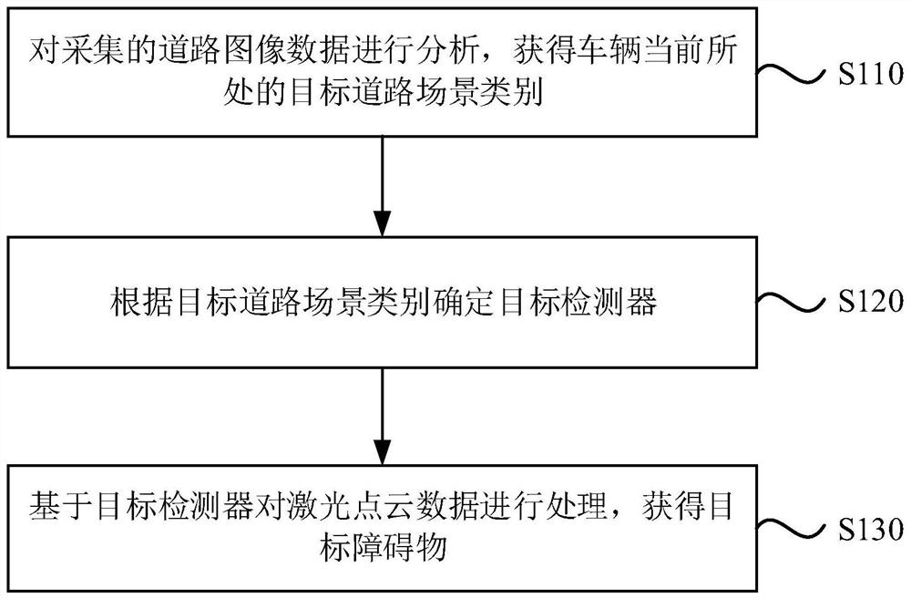
[0042] figure 1 It is a flow chart of a road object detection method provided by Embodiment 1 of the present invention. This embodiment is applicable to the situation of identifying objects around the vehicle. This method can be executed by a road object detection device, such as figure 1 As shown, the method specifically includes the following steps:

[0043] Step 110, analyzing the collected road image data to obtain the target road scene category where the vehicle is currently located.

[0044] Among them, the road image data can be collected by the vehicle camera. The road scene category may include simple road scenes (such as highway scenes) and complex road scenes (such as urban road scenes).

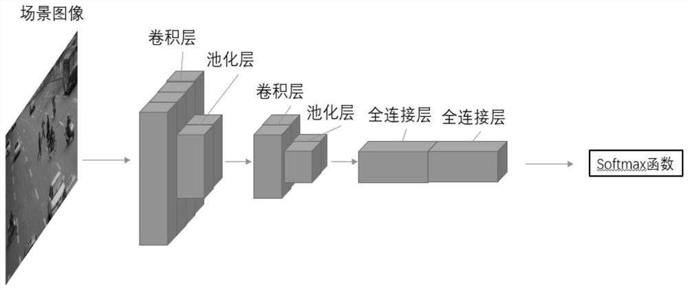
[0045] Specifically, the method of analyzing the collected road image data to obtain the road scene category where the vehicle is currently located may be: input the collected road image data into the road scene classifier, and output the multiple road scene categories where the...

Embodiment 2

[0059] Figure 5 It is a schematic structural diagram of a road object detection device provided in Embodiment 2 of the present invention. Such as Figure 5 As shown, the device includes: a target road scene category acquisition module 210 , a target detector determination module 220 and a target obstacle acquisition module 230 .

[0060] The target road scene category acquisition module 210 is used to analyze the collected road image data to obtain the target road scene category where the vehicle is currently located;

[0061] Target detector determination module 220, for determining the target detector according to the target road scene category;

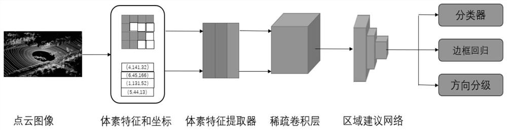
[0062] The target obstacle obtaining module 230 is configured to process the laser point cloud data based on the target detector to obtain the target obstacle.

[0063] Optionally, the target road scene category acquisition module 210 is also configured to: input the collected road image data into the road scene classifier, and...

Embodiment 3

[0076] Image 6 It is a schematic structural diagram of a computer device provided by Embodiment 3 of the present invention. Image 6 A block diagram of a computer device 312 suitable for implementing embodiments of the invention is shown. Image 6 The computer device 312 shown is only an example, and should not impose any limitation on the functions and scope of use of the embodiments of the present invention. Device 312 is a typical computing device for road object detection functions.

[0077] Such as Image 6 As shown, computer device 312 takes the form of a general-purpose computing device. Components of computer device 312 may include, but are not limited to: one or more processors 316, storage 328, bus 318 connecting various system components including storage 328 and processor 316.

[0078] Bus 318 represents one or more of several types of bus structures, including a memory bus or memory controller, a peripheral bus, an accelerated graphics port, a processor, or a...


PUM


Abstract

The embodiment of the invention discloses a road target detection method and device, equipment and a vehicle. The method comprises the following steps of: analyzing acquired road image data to obtaina current target road scene category of a vehicle; determining a target detector according to the target road scene category; and processing the laser point cloud data based on the target detector toobtain a target obstacle. According to the road target detection method provided by the embodiment of the invention, the corresponding detector is selected according to the current road scene categoryof the vehicle to process the laser point cloud data, so that the requirement on the detection speed can be met, and the detection precision can also be ensured.

Description

technical field [0001] The embodiments of the present invention relate to the technical field of unmanned driving, and in particular to a detection method, device, equipment and vehicle of road targets. Background technique [0002] The autonomous driving technology is in its infancy, and safety is the primary problem to be faced in the realization of autonomous driving. The complex road environment and high driving speed make automatic driving have extremely high requirements for the accuracy and real-time performance of the detection algorithm. The current mainstream lidar point cloud detectors are roughly divided into one-stage and two-stage detectors. The one-stage detector has the advantages of fast processing speed, high efficiency, and good real-time performance, but the detection accuracy is slightly worse than the two-stage detector; The detection accuracy of the stage detector is higher, but the real-time performance is worse than that of the stage detector. Cont...

Claims


Application Information

Patent Timeline
Patent Type & Authority Applications(China)
IPC IPC(8): G06K9/00G06K9/62G06N3/04G06N3/08
CPCG06N3/08G06V20/588G06N3/047G06N3/045G06F18/241G06F18/2415
Inventor 李创辉王宇李锦瑭王硕耿真
Owner CHINA FIRST AUTOMOBILE
Why Eureka
Try Eureka