
A Circuit for Improving Load Transient Response of Peak Current Mode DCDC Converter

A peak current mode, load transient technology, applied in related fields, can solve problems such as poor transient response, achieve the effect of increasing frequency, simple and effective circuit implementation, and suppressing the amplitude of overshoot

Active Publication Date: 2022-04-12
SG MICRO
View PDF5 Cites 0 Cited by
  • Summary
  • Abstract
  • Description
  • Claims
  • Application Information

AI Technical Summary

Problems solved by technology

The peak current mode DCDC converter is a more commonly used power conversion technology realized by current mode control. It obtains better dynamic performance and higher output accuracy through the combination of current sampling circuit, error amplifier, PWM comparator and oscillator. etc., but the inventors found that the peak current mode DCDC converter in the prior art has poor transient response when there is a load jump

Method used


Image

  • A Circuit for Improving Load Transient Response of Peak Current Mode DCDC Converter
  • A Circuit for Improving Load Transient Response of Peak Current Mode DCDC Converter
  • A Circuit for Improving Load Transient Response of Peak Current Mode DCDC Converter

Examples


Embodiment Construction

[0017] Below with the accompanying drawings ( Figure 1-Figure 4 ) to illustrate the present invention.

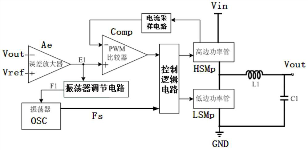
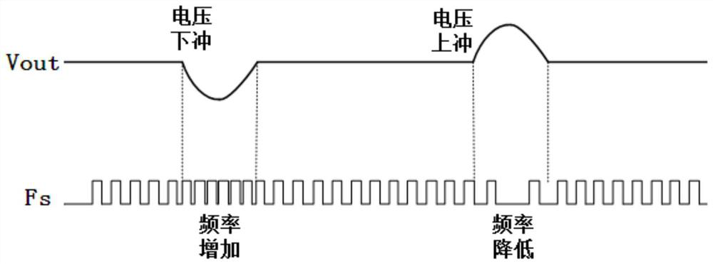
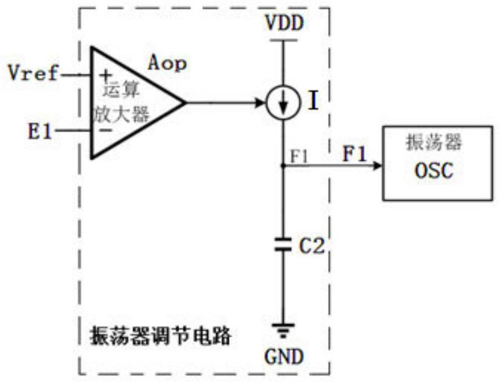
[0018] figure 1 It is a structural schematic diagram of an improved load transient response circuit of a peak current mode DCDC converter implementing the present invention. figure 2 It is the effect diagram of load transient response implementing the circuit of the present invention. image 3 It is a structural schematic diagram of the oscillator adjustment circuit used in the implementation of the present invention. Figure 4 It is a structural schematic diagram of another oscillator adjustment circuit used in the implementation of the present invention. Such as Figure 1 to Figure 4 As shown, a circuit for improving the load transient response of a peak current mode DCDC converter includes a control logic circuit, a comparator Comp and an oscillator OSC, and the output terminal of the comparator Comp is connected to the first input terminal of the control logic cir...


PUM


Abstract

A circuit for improving the load transient response of a peak current mode DCDC converter, which can improve the transient response of the DCDC converter when the load jumps, so as to better reduce the fluctuation of the output voltage or the amplitude of the overshoot and undershoot, and is characterized in that, Including a control logic circuit, a comparator and an oscillator, the output terminal of the comparator is connected to the first input terminal of the control logic circuit, the positive input terminal of the comparator is connected to the output terminal of the error amplifier, and the oscillator The output end of the control logic circuit is connected to the second input end of the control logic circuit, an oscillator adjustment circuit is arranged between the input end of the oscillator and the output end of the error amplifier, and the negative input end of the error amplifier is connected to the output The positive input terminal of the error amplifier is connected to the reference voltage terminal.

Description

technical field [0001] The present invention relates to peak current mode DCDC converter load jump transient response technology, in particular to an improved peak current mode DCDC converter load transient response circuit, by adding an oscillator adjustment circuit between the output terminal of the error amplifier and the oscillator The switching frequency control signal output by the oscillator is changed to improve the transient response of the DCDC converter when the load jumps, so as to better reduce the amplitude of the overshoot or undershoot when the output voltage fluctuates. Background technique [0002] A DCDC converter is a circuit that converts a DC input voltage into another DC voltage value and then outputs it. The peak current mode DCDC converter is a more commonly used power conversion technology realized by current mode control. It obtains better dynamic performance and higher output accuracy through the combination of current sampling circuit, error ampl...

Claims


Application Information

Patent Timeline
Patent Type & Authority Patents(China)
IPC IPC(8): H02M3/158H02M1/14
CPCH02M3/158H02M1/14
Inventor 王宇
Owner SG MICRO
Learn More