Machining and mounting method of rigid suspender of pedestrian suspension bridge
A technology of processing method and installation method, which is applied in the direction of suspension bridges, bridges, bridge parts, etc., can solve the problems of uncoordinated deformation of anchor head and cable body, long production cycle of short slings, high production cost, etc., and achieve great promotion and application value, Improved permeability and aesthetics, low production cost
- Summary
- Abstract
- Description
- Claims
- Application Information
AI Technical Summary
Problems solved by technology
Method used
Image
Examples
Embodiment 1
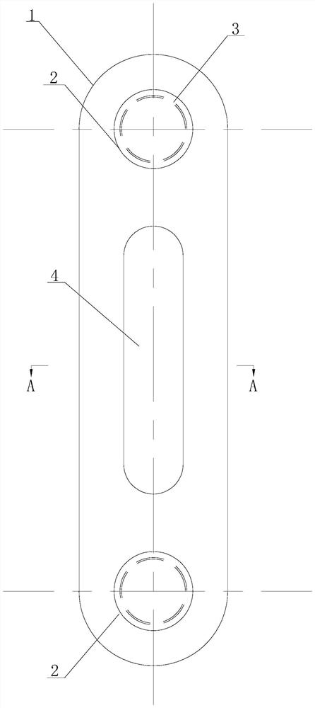
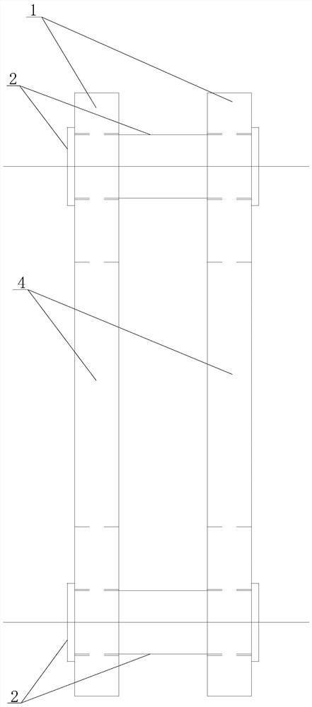
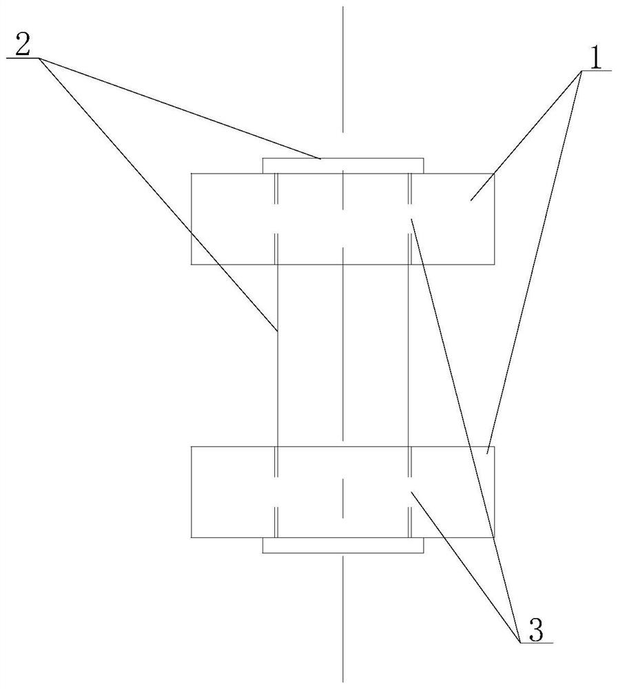
[0070] The rigid suspension rod of the pedestrian suspension bridge in this embodiment comprises a flat plate 1, a pin shaft 2, a pin hole 3 and a ventilation hole 4. A pin hole 3 is respectively arranged at both ends of the flat plate 1, and a pin hole 3 is respectively installed in each pin hole 3. The pin shaft 2, the pin shaft 2 runs through the flat plate 1, the ventilation hole 4 is arranged in the middle of the flat plate 1, and the ventilation hole 4 is arranged in a waist-shaped structure.
[0071] The center points of the two pin holes 3 in this embodiment are all located on the axis of the flat plate 1, and the two ends of the flat plate 1 are respectively equipped with a cable clamp lug 5 and a beam upper lug 6, and the cable clamp lug 5 and a pin shaft 2 Connection, the lifting lug 6 on the beam is connected with another pin 2.
[0072] The flat plate 1 in this embodiment is arranged vertically, and the center of the cable clamp ear plate 5 and the center of the l...
Embodiment 2
[0080] The rigid suspension rod of the pedestrian suspension bridge in this embodiment comprises a flat plate 1, a pin shaft 2, a pin hole 3 and a ventilation hole 4. A pin hole 3 is respectively arranged at both ends of the flat plate 1, and a pin hole 3 is respectively installed in each pin hole 3. The pin shaft 2, the pin shaft 2 runs through the flat plate 1, the ventilation hole 4 is arranged in the middle of the flat plate 1, and the ventilation hole 4 is arranged in a waist-shaped structure.
[0081] The center points of the two pin holes 3 are located on the axis of the flat plate 1, and the two ends of the flat plate 1 are respectively equipped with a cable clip lug 5 and a beam upper lug 6, the cable clamp lug 5 is connected with a pin shaft 2, and the beam upper lug 6 6 is connected with another bearing pin 2.
[0082] The flat plate 1 in this embodiment is arranged vertically, and the center of the cable clamp ear plate 5 and the center of the lifting lug 6 on the ...
Embodiment 3
[0093] The processing method of the rigid suspender of the pedestrian suspension bridge in the present embodiment is used to process the rigid suspender of the pedestrian suspension bridge in embodiment 1 and embodiment 2, and the processing method is as follows:
[0094] 1. The flat plate 1 is processed and formed by a whole steel plate, and is cut and opened by numerical control plasma cutting technology.
[0095] 2. The plate 1 should check the grade, thickness and surface quality of the steel plate before blanking, and the blank can only be blanked after passing the inspection.
[0096] 3. Carry out a comprehensive inspection of the CNC machine tool before operation; check whether the empty car is running normally according to the procedure. Draw the component installation position line, alignment line and inspection line.
[0097] 4. When cutting the edge and opening of the steel plate, first lift the steel plate to the cutting platform and fix it in place, and remove th...
PUM
 Abstract
Description
Claims
Application Information
 - R&D
- Intellectual Property
- Life Sciences
- Materials
- Tech Scout
- Unparalleled Data Quality
- Higher Quality Content
- 60% Fewer Hallucinations
Browse by: Latest US Patents, China's latest patents, Technical Efficacy Thesaurus, Application Domain, Technology Topic, Popular Technical Reports.
© 2025 PatSnap. All rights reserved.Legal|Privacy policy|Modern Slavery Act Transparency Statement|Sitemap|About US| Contact US: help@patsnap.com


