Tool for alignment outside machine tool during machining of FMS architecture

A machine tool and frame technology, applied to metal processing machinery parts, manufacturing tools, metal processing equipment, etc., can solve the problems of insufficient positioning accuracy, non-compliance, and inability to align, and achieve easy operation, easy disassembly, and practicality. strong effect

Pending Publication Date: 2020-11-27
河北京车轨道交通车辆装备有限公司
View PDF0 Cites 0 Cited by
  • Summary
  • Abstract
  • Description
  • Claims
  • Application Information

AI Technical Summary

Problems solved by technology

The traditional scribing and alignment method not only has insufficient positioning accuracy, but also needs to complete the work in the machine tool like the fixture positioning method, which does not meet the above-mentioned FMS flexible production line requirements
That is to say, the existing FMS flexible production line cannot achieve alignment outside the machine tool before processing the frame. Therefore, how to propose a high-precision technical means suitable for alignment outside the machine tool to truly realize the operation of the entire FMS line , is a problem to be solved urgently in this industry and the present invention

Method used


Image

  • Tool for alignment outside machine tool during machining of FMS architecture
  • Tool for alignment outside machine tool during machining of FMS architecture
  • Tool for alignment outside machine tool during machining of FMS architecture

Examples


Embodiment 1

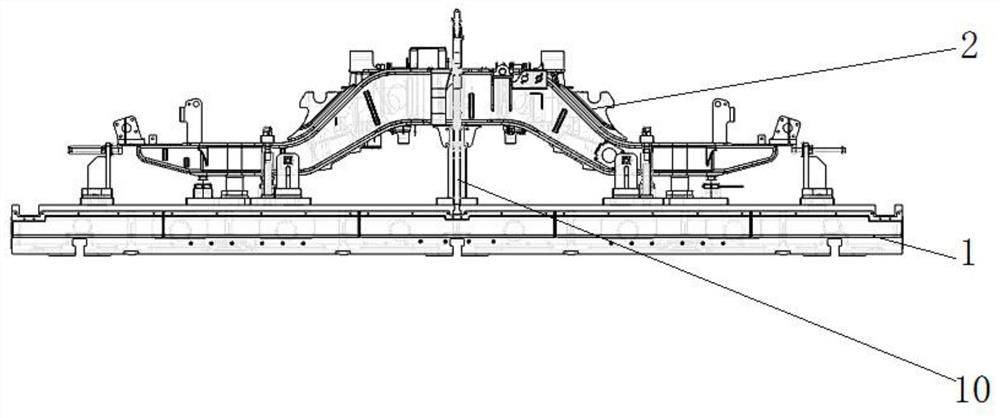
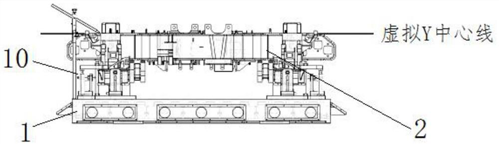
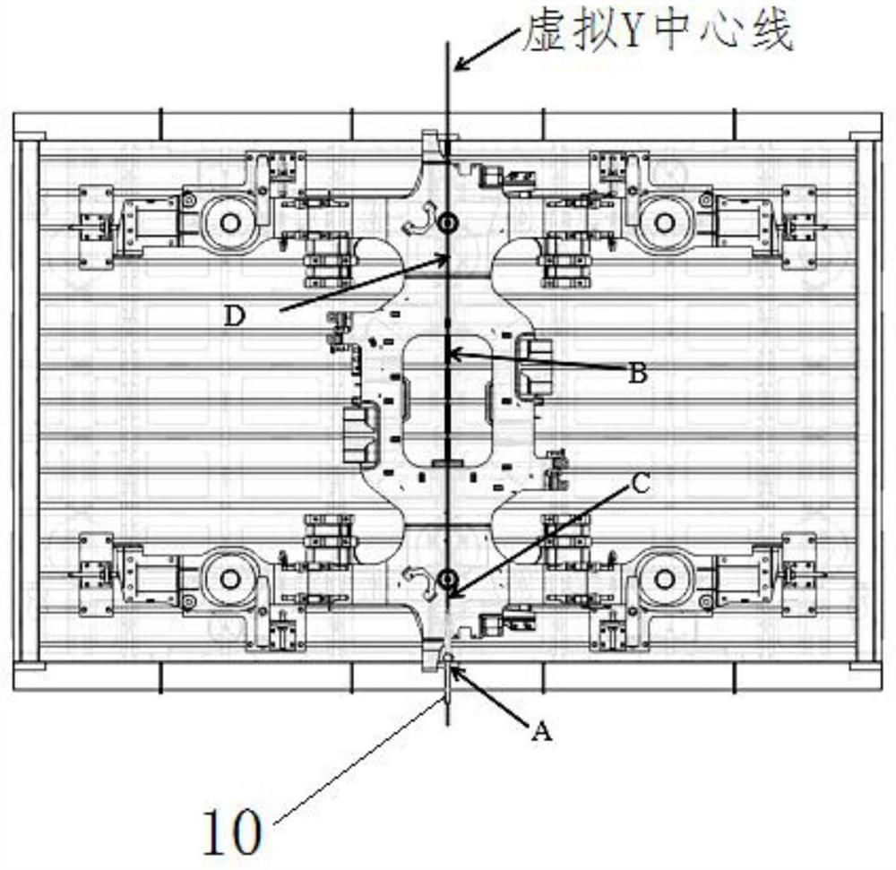
[0041] Such as Figure 1-6 As shown, the present embodiment provides a tool 10 for aligning outside the machine tool during FMS frame processing, which mainly includes a sliding seat 3 , a sleeve rod assembly 4 and a tip rod 5 . Wherein, the sliding seat 3 is used to be slidably installed in the T-shaped chute of the workbench 1, and the T-shaped chute extends along the virtual Y centerline in the figure; the sleeve rod assembly 4 is preferably mounted on the sliding seat 3 in a detachable manner, And the sleeve rod assembly 4 can realize height adjustment and circumferential rotation adjustment; the top rowing rod 5 is preferably installed on the top of the sleeve rod assembly 4 in a detachable manner, and the top rowing rod 5 can carry out tip telescopic adjustment relative to the sleeve rod assembly 4, Tip lifting adjustment and tip rotation adjustment, the adjustment range of the top rowing rod 5 is located in the plane where the top rowing rod 5 and the sleeve rod assembl...


PUM


Abstract

The invention discloses a tool for alignment outside a machine tool during machining of an FMS architecture, and relates to the technical field of flexible manufacturing. The tool mainly comprises a slide seat, a sleeve rod assembly and a tip scratching rod, wherein the slide seat is used for being glidingly arranged on a work table; the sleeve rod assembly is arranged on the slide seat, and can realize height regulation and/or peripheral rotation regulation; and the tip scratching rod is arranged on the top of the sleeve rod assembly, and can perform tip telescopic regulation, tip ascending and descending regulation and/or tip rotation regulation relative to the sleeve rod assembly. The tool has the advantages that the structure is simple and reasonable; the operation is easy; the mounting and dismounting taking is convenient; the design is performed by ingeniously using a principle that a T-shaped groove of the work table is parallel to the coordinate system of the machine tool; thegoal of completing component alignment through a drawn line without a machine tool cross beam and a main shaft is fast and simply achieved; the problem that automatic operation cannot be realized during FMS automatic production is solved; and meanwhile, a traditional thesis that a workpiece cannot be aligned without the machine tool in the industry is broken through.

Description

technical field [0001] The invention relates to the technical field of flexible manufacturing, in particular to a tool for alignment outside a machine tool during FMS frame processing. Background technique [0002] There are generally two ways to align the workpiece on the machine tool: one is the positioning of the marking alignment method, and the other is the alignment and positioning of the fixture. Marking and alignment method positioning, that is, using a stylus on the machine tool to align the workpiece according to the line segment that is pre-marked on the blank or semi-finished product to obtain the correct position. This method is limited by the marking accuracy and alignment accuracy, and the positioning accuracy is not high. It is mainly used for rough machining with small batches, low blank precision, large parts and inconvenient processing with fixtures. The use of fixture positioning is a positioning method that directly uses the positioning elements on the ...

Claims


Application Information

Patent Timeline
Patent Type & Authority Applications(China)
IPC IPC(8): B23Q1/72B23Q17/00B25H7/04
CPCB23Q1/72B23Q17/00B25H7/04
Inventor 郭光伟李增楼史大伟齐思宇李江新范保岐
Owner 河北京车轨道交通车辆装备有限公司
Why Eureka
Try Eureka