
Self-cleaning type garbage transport vehicle

A garbage transport vehicle and self-cleaning technology, which is applied in the direction of garbage collection, garbage cleaning, garbage storage, etc., can solve the problems of manpower consumption and difficulty in cleaning garbage trucks, so as to reduce manpower, improve cleaning efficiency, and improve cleaning efficiency Effect

Active Publication Date: 2020-11-27
安徽省皖工电动车科技有限公司
View PDF10 Cites 0 Cited by
  • Summary
  • Abstract
  • Description
  • Claims
  • Application Information

AI Technical Summary

Problems solved by technology

[0004] The purpose of the present invention is to solve the problem of difficult and labor-intensive cleaning of garbage trucks in the prior art, and propose a self-cleaning garbage truck

Method used


Image

  • Self-cleaning type garbage transport vehicle
  • Self-cleaning type garbage transport vehicle
  • Self-cleaning type garbage transport vehicle

Examples


Embodiment 1

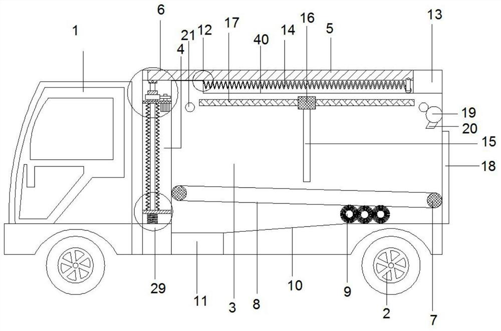
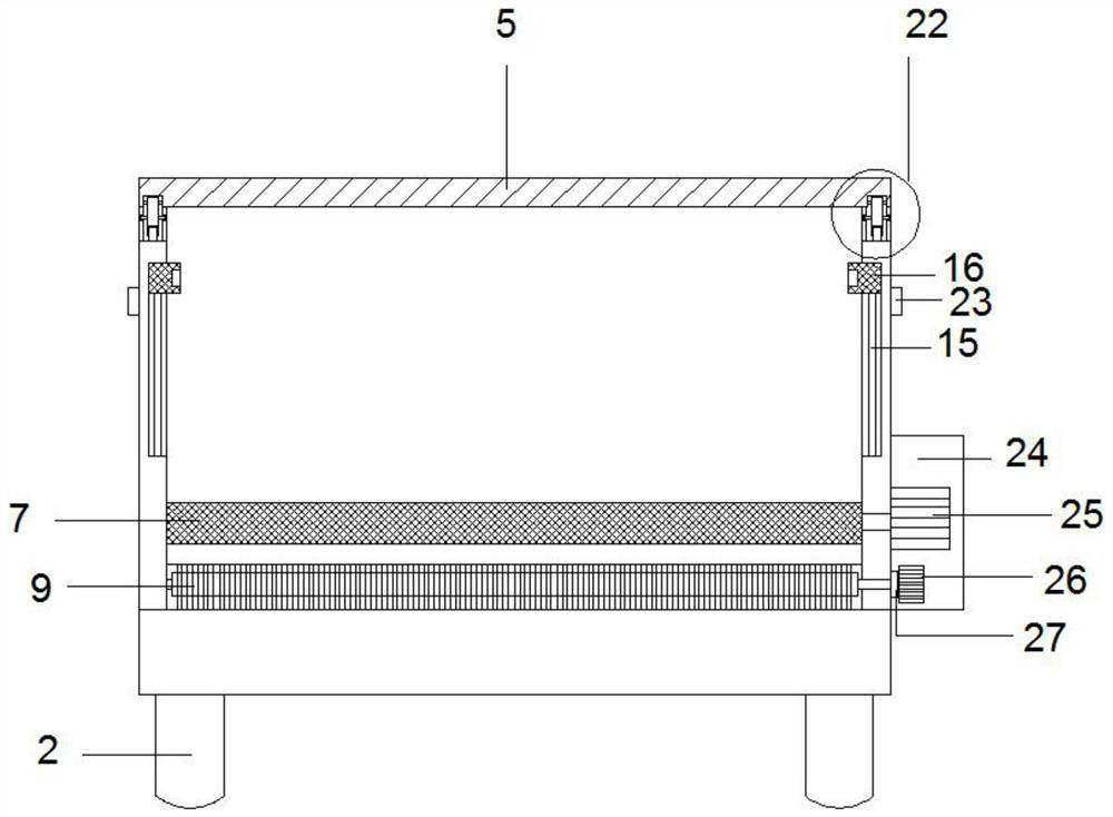
[0030] refer to Figure 1-7 , a self-cleaning garbage transport vehicle, comprising a front 1, tires 2 and a compartment 3 connected behind the front 1, the tire 2 is arranged under the front 1 and the compartment 3, side panels 13 are provided on the front and rear sides of the compartment 3 , a cover plate 5 is arranged above the compartment 3, a first chute 40 is provided at the center of the upper end of the side plate 13, and a sliding mechanism 22 is provided at the lower end of the right side of the cover plate 5 to be slidably connected with the first chute 40, and the first chute The inner left end of 40 is connected with the sliding mechanism 22 through the first elastic member 14. The side of the compartment 3 close to the front 1 is provided with a protective layer 4, and the upper end of the protective layer 4 is provided with a lifting mechanism 6. The lifting mechanism 6 includes Screw rod 30, fixed plate 31 and rotating sleeve 32, described fixed plate 31 is fi...

Embodiment 2

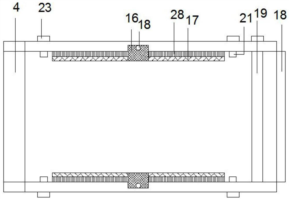
[0038] like Figure 1-7 As shown, this embodiment is basically the same as Embodiment 1. Preferably, electric guide rails 15 are arranged symmetrically inside the side plates 13 on the front and rear sides of the compartment 3, and the electric guide rails 15 are embedded in the inside of the side plates 13, and the electric guide rails 15 are covered with An electric sliding sleeve 16 is provided, and horizontal brushes 17 are arranged symmetrically on both sides of the electric sliding sleeve 16 , and horizontal brush bristles 28 on the horizontal brush 17 are slidingly connected to the surface of the side plate 13 . In order to further clean the side panels 13 of the compartment 3 .

[0039] Working principle: when filling garbage, start the third motor 34, so that the second gear 33 drives the rotating sleeve 32 to rotate, so that the screw 30 drives one end of the cover plate 5 to rise, and the other end slides with the side plate 13 to open the top of the compartment 3, ...


PUM


Abstract

The invention discloses a self-cleaning type garbage transport vehicle, and relates to the technical field of garbage transport vehicle cleaning. The garbage transport vehicle comprises a vehicle head, tires and a carriage; side plates are arranged on the front side and the rear side of the carriage; a cover plate is arranged above the carriage; slide grooves are formed in the upper end of the side plates; a sliding mechanism is arranged at the lower end of the right side of the cover plate; a protective layer is arranged on one side of the carriage; a lifting mechanism is arranged at the upper end inside the protective layer; the lifting mechanism comprises a screw rod, a fixed plate and a rotating sleeve; the sliding mechanism comprises a slide column and a rotating wheel; second spraying ports are formed in both the left and right sides of the inner side upper ends of the side plates; traction rollers are arranged on two sides at the bottom of the carriage; the traction rollers areconnected by a transmission caterpillar band; and a plurality of cleaning roller brushes are arranged between the lower part of the transmission caterpillar band and the bottom of the carriage. The garbage transport vehicle overcomes the deficiencies of the prior art, use is convenient, high-efficiency and rapid cleaning of the garbage transport vehicle can be realized, and the cleaning efficiencyof the garbage transport vehicle can be improved.

Description

technical field [0001] The invention relates to the technical field of cleaning garbage transport vehicles, in particular to a self-cleaning garbage transport vehicle. Background technique [0002] Garbage trucks are mainly used to transport all kinds of garbage. They are generally equipped with larger compartments for carrying garbage. After being filled with garbage, the garbage truck transports the garbage to the garbage treatment plant and then cleans up after dumping the garbage. After dumping, it is usually necessary to clean the interior of the garbage truck to prevent bacterial growth and pollution caused by the long-term use of the garbage truck. [0003] The traditional cleaning method usually requires manual washing with a water pipe and then scrubbing, which is time-consuming and laborious, and is inconvenient to operate, which brings great troubles to actual use. Contents of the invention [0004] The object of the present invention is to solve the problem of...

Claims


Application Information

Patent Timeline
Patent Type & Authority Applications(China)
IPC IPC(8): B65F7/00B65F3/12
CPCB65F7/005B65F3/12Y02W30/10
Inventor 张胡记徐长春王和青
Owner 安徽省皖工电动车科技有限公司
Learn More