Femtosecond heterodyne optical Kerr gate and imaging device and method based on the optical Kerr gate

An imaging device and optical Kerr technology, applied in optics, nonlinear optics, instruments, etc., can solve the problems of blurred image edges, affect imaging quality, and reduce system imaging resolution, and achieve sharp imaging edges and high system resolution. , sharp edge effect

Active Publication Date: 2016-02-24
XI AN JIAOTONG UNIV
View PDF2 Cites 0 Cited by
  • Summary
  • Abstract
  • Description
  • Claims
  • Application Information

AI Technical Summary

Problems solved by technology

However, this low-pass filtering effect also leads to blurred image edges in traditional optical Kerr gate imaging technology, which affects its imaging quality and even greatly reduces its system imaging resolution.

Method used


Image

  • Femtosecond heterodyne optical Kerr gate and imaging device and method based on the optical Kerr gate
  • Femtosecond heterodyne optical Kerr gate and imaging device and method based on the optical Kerr gate
  • Femtosecond heterodyne optical Kerr gate and imaging device and method based on the optical Kerr gate

Examples


Embodiment 1

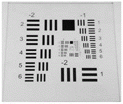
[0063] In this embodiment, a discriminative rate board exposed to the air (U.S. military standard 1951USAF resolution board, conforming to the U.S. MIL-STD-150A standard) is used as the sample to be tested. The pattern on the discriminator plate includes several groups of three short lines, the size of the short lines is from large to small. This test pattern is widely used to test the resolution of optical imaging systems (such as microscopes and cameras). figure 2 Images of this resolution board were taken directly with a digital camera. The specific implementation steps are as follows:

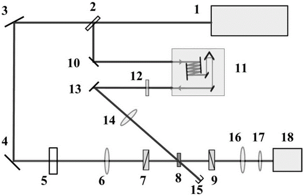
[0064] (1) The single pulse energy emitted from the femtosecond laser is 3mJ, the pulse width is 50fs, the repetition frequency is 1kHz, and the femtosecond pulse laser is polarized in the horizontal direction. After being limited by an aperture of about 4mm, the beam splitting ratio is 2 The :8 beam splitter is divided into two beams, one of which has a stronger light intensity is the fe...

Embodiment 2

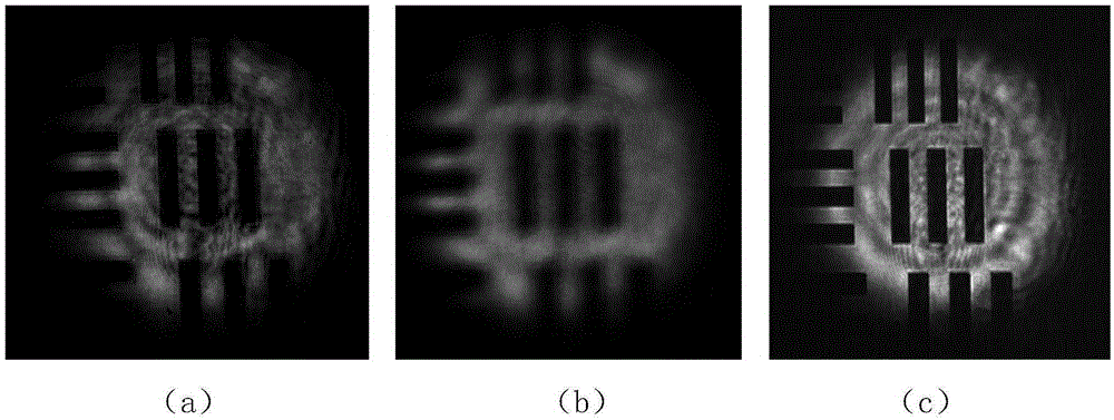
[0071] In this embodiment, the discriminative rate plate hidden in polystyrene microsphere suspension is used as the sample to be tested, simulating the ability of the present invention to image hidden objects in a large number of scattering environments. The discriminative rate plate was as described in Example 1. The specific implementation steps are as follows:

[0072] (1) A small amount of polystyrene microspheres with a particle size of 15 microns was mixed into deionized water to prepare polystyrene microsphere suspension. This suspension is a commonly used standard scattering medium. By adjusting the concentration of polystyrene microspheres, a strong scatterer with an optical density of 10 was obtained. The identification rate plate is placed in front of the scattering medium to constitute the sample to be tested in this example.

[0073] (2) The single pulse energy emitted from the femtosecond laser is 3mJ, the pulse width is 50fs, the repetition frequency is 1kHz...


PUM

PropertyMeasurementUnit
sizeaaaaaaaaaa
optical densityaaaaaaaaaa

Abstract

A femtosecond heterodyne optical Kerr gate and an imaging device and method based on the optical Kerr gate. The detection optical path of the imaging device is sequentially provided with the target to be measured, a femtosecond heterodyne optical Kerr gate composed of a polarizer, an optical Kerr medium and a polarizer, and a CCD; and the polarization direction of the polarizer and the detection pulse The vertical direction of polarization has a heterodyne angle of 3-5°; the switching optical path is provided with an optical delay line and a half-wave plate in sequence, and the switching pulse and the detection pulse overlap in the optical Kerr medium. The imaging method is as follows: the femtosecond pulse is divided into two channels, the detection pulse is incident on the sample to be tested, and enters the femtosecond heterodyne optical Kerr gate after reflection and transmission; The component of the detection pulse that carries the sample topography information is incident on the CCD by the gated detection pulse to obtain a topography image of the sample to be tested with ultra-high time resolution. The invention has the advantages of simple optical path, very short gate time, imaging spatial resolution close to system diffraction limit and the like.

Description

technical field [0001] The invention belongs to the technical field of ultra-fast imaging and measurement, and relates to a femtosecond heterodyne optical Kerr gate and an imaging device and method based on the optical Kerr gate. Background technique [0002] The development of ultra-fast imaging and measurement technology has important application value in the research fields of high-speed collision, detonation process, high-voltage discharge, visual mechanism and other transient processes. Generally, high time-resolved imaging from milliseconds to sub-picoseconds can be achieved by using photoelectric technology. Using ultra-fast imaging technology based on photonic technology, such as femtosecond holographic imaging and nonlinear optical gate imaging technology. [0003] Optical Kerr gate imaging technology is a typical nonlinear optical gate imaging technology. This imaging technology uses the optical shutter constructed by the optical Kerr effect, which is usually cal...

Claims


Application Information

Patent Timeline
Patent Type & Authority Patents(China)
IPC IPC(8): G02F1/35G03B39/00
Inventor 谭文疆司金海占平平许士超陈烽侯洵
Owner XI AN JIAOTONG UNIV
Why Eureka
Try Eureka