
Concrete cast-in-situ type green plant planting waterproof cushion

A waterproof cushion and concrete technology, applied in planting substrates, automatic watering devices, roof drainage, etc., can solve the problems of soil corrosion, inability to obtain water absorption in time, death, etc., to avoid the withering or death of vegetation, improve water Resource utilization, effect of increasing water storage

Inactive Publication Date: 2020-11-27
JIANGSU XIYI HIGH NEW DISTRICT TECH DEV CO LTD
View PDF0 Cites 2 Cited by
  • Summary
  • Abstract
  • Description
  • Claims
  • Application Information

AI Technical Summary

Problems solved by technology

[0002] In order to beautify the environment, reduce noise, reduce dust and heat insulation, some green plants are generally planted on the roof. After the prepared water or rainwater is poured, it will be absorbed by the planting soil, and the water will penetrate downward, which will cause damage to the concrete structure. The traditional waterproof structure, Generally, a waterproof membrane is installed on the surface of the concrete. This kind of waterproof structure is simple and is corroded by the soil, which makes the waterproof effect poor. Moreover, the traditional concrete top planting has poor penetration resistance. It penetrates and grows along the gaps on the surface of the concrete pouring layer, thereby destroying the concrete structure and reducing the waterproof performance. At the same time, the vegetation is directly exposed to light, and the water evaporates quickly. Because the water cannot be absorbed in time, it is easy to cause the vegetation to wither or die. Therefore, the design of a It is necessary to plant a concrete cast-in-place green planting waterproof cushion

Method used


Image

  • Concrete cast-in-situ type green plant planting waterproof cushion
  • Concrete cast-in-situ type green plant planting waterproof cushion
  • Concrete cast-in-situ type green plant planting waterproof cushion

Examples


Embodiment Construction

[0018] The following will clearly and completely describe the technical solutions in the embodiments of the present invention with reference to the accompanying drawings in the embodiments of the present invention. Obviously, the described embodiments are only some, not all, embodiments of the present invention. Based on the embodiments of the present invention, all other embodiments obtained by persons of ordinary skill in the art without making creative efforts belong to the protection scope of the present invention.

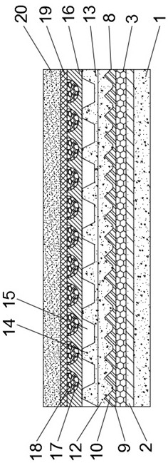
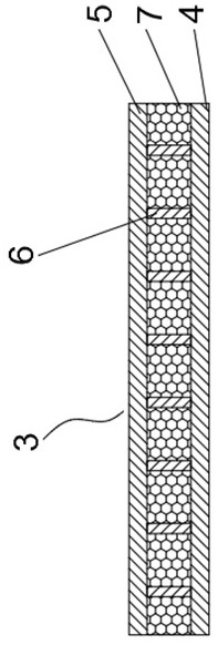
[0019] see Figure 1-3 , the present invention provides a technical solution: a concrete cast-in-place green planting waterproof cushion layer, including a base layer 1, a waterproof coiled material layer 2, an insulation layer 3, an anti-crack layer 8, a drainage layer 13, a drainage protrusion 14, Drainage tank 15, water storage layer 16, groove 17, sponge 18, water filter layer 19 and planting layer 20, the upper end of base layer 1 is provided with waterpr...


PUM


Abstract

The invention discloses a concrete cast-in-situ type green plant planting waterproof cushion. The concrete cast-in-situ type green plant planting waterproof cushion comprises a base layer, a waterproof roll layer, an insulation layer, an anti-cracking layer, a drainage layer, a water storage layer, a water filter layer and a planting layer. The waterproof roll layer is arranged at the upper end ofthe base layer. By arranging the water storage layer, water permeates downward. By arranging a groove and sponge, the water storage efficiency can be improved greatly, and water stored in the grooveis unlikely to run off, so that the utilization ratio of a water resource is improved. Meanwhile, the water storage amount is increased for planting, so that a condition that vegetation dies away or dies due to belated water supplement is avoided. Permeating into the drainage layer, water can flow out outward from a drainage channel, so that damage to the structure due to water accumulation in a concrete structure is avoided. By arranging the anti-cracking layer, a concrete pouring layer is connected and fastened to a bump on the surface of a water isolating board to play an anti-cracking role, so that the anti-cracking property of the integral structure is improved, cracks are avoided, and water permeates downward, so that the waterproof performance of the structure is improved.

Description

technical field [0001] The invention relates to the technical field of waterproofing, in particular to a concrete cast-in-place waterproof cushion for planting green plants. Background technique [0002] In order to beautify the environment, reduce noise, reduce dust and heat insulation, some green plants are generally planted on the roof. After the prepared water or rainwater is poured, it will be absorbed by the planting soil, and the water will penetrate downward, which will cause damage to the concrete structure. The traditional waterproof structure, Generally, a waterproof membrane is installed on the surface of the concrete. This kind of waterproof structure is simple and is corroded by the soil, which makes the waterproof effect poor. Moreover, the traditional concrete top planting has poor penetration resistance. It penetrates and grows along the gaps on the surface of the concrete pouring layer, thereby destroying the concrete structure and reducing the waterproof p...

Claims


Application Information

Patent Timeline
Patent Type & Authority Applications(China)
IPC IPC(8): E04D11/02E04D13/00E04D13/04E04D13/16A01G24/44A01G27/06
CPCA01G27/06A01G24/44E04D11/02E04D13/00E04D13/04E04D13/16Y02B80/32Y02A30/254
Inventor 殷邗清
Owner JIANGSU XIYI HIGH NEW DISTRICT TECH DEV CO LTD
Learn More