Multi-plunger cooperative gas-lift liquid drainage technology

A multi-plunger, gas lift technology, which is applied in liquid fuel engines, liquid variable capacity machinery, and production fluids, etc. Small ratio, the effect of reducing the gas-liquid ratio

Active Publication Date: 2020-11-27
贺信
View PDF6 Cites 1 Cited by
  • Summary
  • Abstract
  • Description
  • Claims
  • Application Information

AI Technical Summary

Problems solved by technology

[0005] Foam drainage technology has disadvantages such as continuous or intermittent manual injection of foam agent into the well, large gas-liquid ratio, small drainage volume, and defoaming treatment after the liquid is discharged from the ground.
The effect of this technology is limited for wells with defoaming effects such as oil in the liquid

Method used


Image

  • Multi-plunger cooperative gas-lift liquid drainage technology
  • Multi-plunger cooperative gas-lift liquid drainage technology
  • Multi-plunger cooperative gas-lift liquid drainage technology

Examples


Embodiment 1

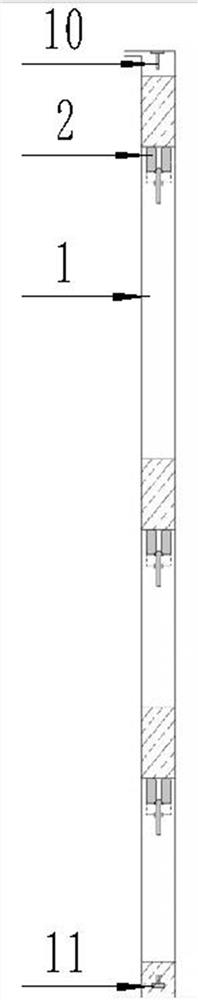
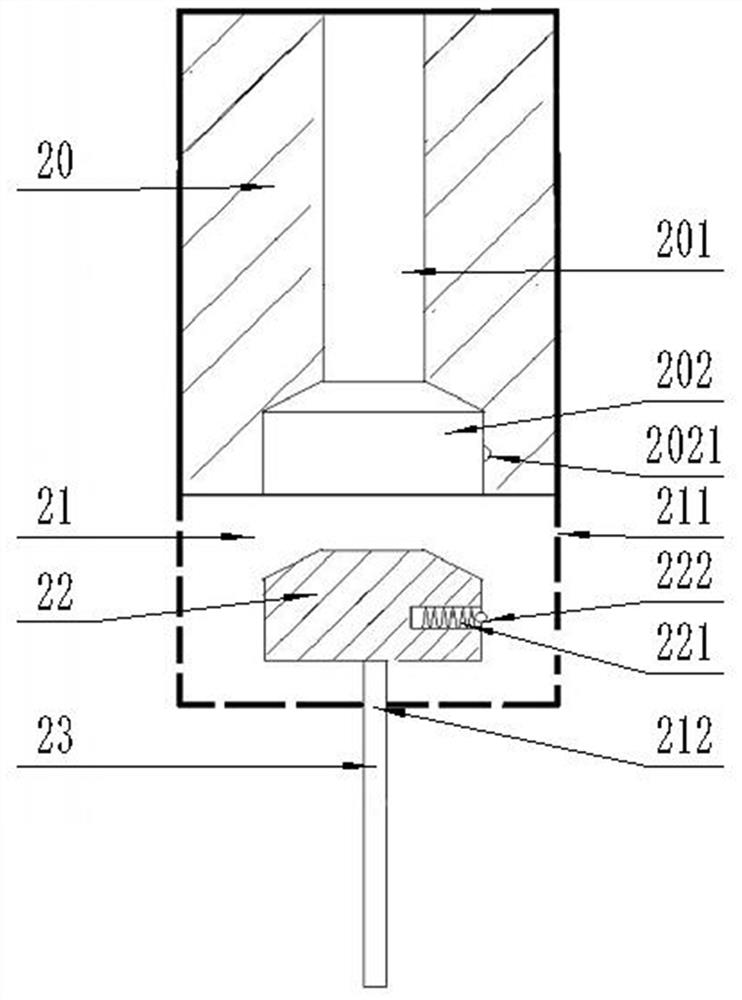
[0033] Such as Figure 1~Figure 5 As shown, a multi-plunger cooperative gas lift drainage technology is applied in the multi-plunger cooperative gas lift drainage system. There are several plungers 2 inside, the top of the tubing 1 is provided with a wellhead poking rod 10, the bottom of the tubing 1 is provided with a retainer 11, the plunger 2 includes a valve body 20, and a cavity 21 connected to the lower part of the valve body 20 is arranged in the cavity. The valve body 22 in the chamber 21 is fixedly connected to the valve rod 23 at the lower part of the valve body 22 and passes through the bottom of the cavity 21. The valve body 20 is provided with a through hole 201 that runs through the upper end surface of the valve body 20, and the lower part of the through hole 201 communicates with a The valve seat hole 202 runs through the lower end surface of the valve body 20 , and a plurality of mesh holes 211 are arranged on the surface of the cavity 21 .

[0034] Multi-plu...

Embodiment 2

[0046] Based on Embodiment 1, an anti-falling spring 221 is provided on the outer surface of valve 22 through the blind hole opened, and an anti-falling boss 222 is provided at the end of the anti-falling spring 221, and an anti-falling boss 222 is provided on the inner surface of the valve seat hole 202. 222 cooperates with the anti-falling hole 2021 to prevent the valve body 22 from falling off. The design of the structure here can improve the stability of the system operation and the fault tolerance rate. In the absence of this structure, the valve body 20 is combined with the valve body 22. Under the action of pressure, the structure is in a sealed state, which can better complete the draining work, but in the case of certain defects in the structure, the anti-falling spring 221 can bear part of the pressure to ensure the stability of the entire draining system.

[0047] The number of anti-falling springs 221 can be multiple, and evenly distributed on the outer surface of t...

Embodiment 3

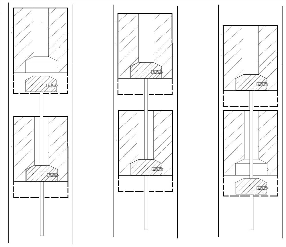
[0049] Based on the first embodiment, the gas at the bottom of the oil pipe can be continuously injected from the ground through the casing to the bottom of the oil pipe. In this case, the application of the multi-stage plunger is even more important. The multi-stage plunger makes the gas column expand step by step. At the same time, the upward movement of the plunger and the liquid column above it is accelerated, the required gas-liquid ratio is reduced, and the liquid discharge volume is increased. In the case of the same liquid discharge volume, the gas volume required by the liquid discharge system is greatly reduced, which can save more manpower. and physical costs.


PUM


Abstract

The invention relates to a multi-plunger cooperative gas-lift liquid drainage technology. The technology is applied to a multi-plunger cooperative gas-lift liquid drainage system, the liquid drainagesystem operates circularly in a reciprocating mode, a plurality of plungers divide a large-section liquid column and a gas column in an oil pipe into multiple sections of liquid columns, the plungersand the gas columns are connected in series, and the plungers are connected in the oil pipe vertically and mutually to achieve liquid load cooperative work. Liquid is drained from a shaft step by step, pressure formed by a small section of liquid column disappears when each small section of liquid column is drained, the pressure of each stage of gas column below the small section of liquid columnis reduced, the volume is expanded, the gas columns are expanded step by step, and meanwhile, gas expansion can be fully utilized to accelerate the plungers and the liquid columns above the plungers to ascend, the needed gas-liquid ratio is reduced, and liquid drainage mount is increased. Under the condition of the same gas amount, more liquid can be drained, or under the condition of the same liquid drainage amount, the gas amount required by the liquid drainage system is greatly reduced.

Description

technical field [0001] The invention relates to the development field of oil and natural gas wellbore relying on its own energy or gas injection, gas lift and liquid drainage, and more specifically relates to a multi-plunger coordinated gas lift and liquid drainage technology. Background technique [0002] After the gas well is put into production, as the production time prolongs, fluid accumulation will gradually appear in some wellbores, and production will begin to be affected by fluid accumulation. Reasonable technology needs to be adopted to remove it in time to maintain the normal and stable production of the gas well. When the formation energy is sufficient, oil and gas wells can be produced by self-spraying and carrying liquid; when the formation energy is reduced enough to maintain self-spraying and carrying liquid production, it is necessary to supplement energy and switch to artificial lift for production. Commonly used artificial lift methods include gas lift, ro...

Claims


Application Information

Patent Timeline
IPC IPC(8): E21B43/00F04B47/12F04B53/14F04B53/10
CPCE21B43/122F04B47/12F04B53/14F04B53/10
Inventor 贺信
Owner 贺信
Why Eureka
Try Eureka