
Pixel-level target positioning method based on laser and monocular vision fusion

A monocular vision, target positioning technology, applied in the direction of using optical devices, measuring devices, instruments, etc., can solve the problem of computing resource consumption, object positioning accuracy, effective positioning distance and cost, limited computing power of terminal computing equipment, and difficult objects. positioning and other problems, to achieve the effect of improving autonomous operation ability, ensuring real-time positioning, and high positioning accuracy

Active Publication Date: 2020-11-27
ZHEJIANG UNIV
View PDF9 Cites 12 Cited by
  • Summary
  • Abstract
  • Description
  • Claims
  • Application Information

AI Technical Summary

Problems solved by technology

At present, depth sensors such as binocular vision, laser radar, and millimeter-wave radar are usually used in the perception system for object positioning. There are still obvious deficiencies in positioning accuracy, effective positioning distance and cost
Since intelligent autonomous operation equipment is constrained by issues such as cost, volume, and power consumption, the computing power of the terminal computing equipment it carries is relatively limited. Therefore, the object positioning method using the above scheme is expensive, has poor real-time performance, and has limited positioning range. It is difficult to effectively complete the precise positioning of objects under the actual working conditions of the equipment

Method used


Image

  • Pixel-level target positioning method based on laser and monocular vision fusion
  • Pixel-level target positioning method based on laser and monocular vision fusion
  • Pixel-level target positioning method based on laser and monocular vision fusion

Examples


Embodiment Construction

[0030] In order to make the purpose, technical solution and advantages of the present invention clearer, the present invention will be further described in detail below in conjunction with the accompanying drawings.

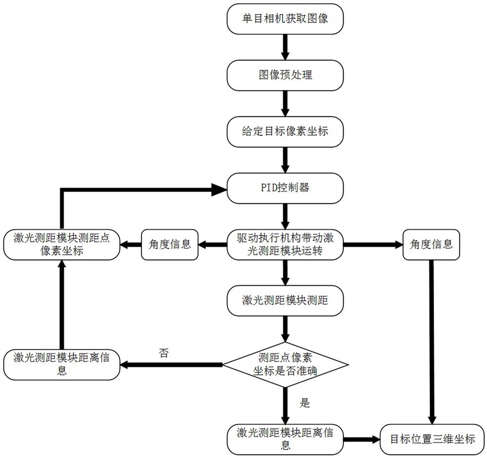
[0031] Such as Figure 1-2 As shown, a pixel-level target positioning method based on laser and monocular vision fusion of the present invention includes the following steps:

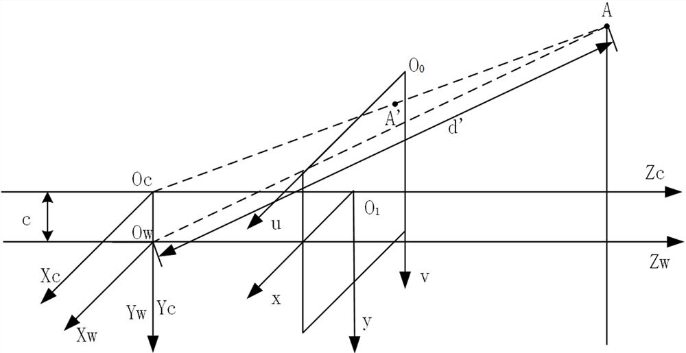
[0032] S1. The installation position of the camera ensures that the optical axis of the camera is parallel to the ground. The installation position of the laser ranging module ensures that the line connecting the optical center of the laser ranging module and the optical center of the camera is perpendicular to the ground and makes the vertical distance between the laser ranging module and the monocular camera spacing as small as possible, where O W x W Y W Z W The coordinate system of the laser ranging module is the world coordinate system of this system, O C x C Y C Z C is the ca...


PUM


Abstract

The invention relates to the field of object three-dimensional positioning methods, and particularly relates to a pixel-level target positioning method based on laser and monocular vision fusion. Themethod comprises the steps of firstly, mounting a camera and a laser ranging module; constructing a coordinate system, calibrating the distance measurement relative positions of the monocular camera and the laser ranging module to obtain calibration parameters, acquiring an environment image through the monocular camera, and then carrying out preprocessing, determining pixel coordinates of a to-be-positioned target; then driving an actuating mechanism through e PID feedback control to drive the laser ranging module to rotate to acquire data and perform calculation; and finally, driving the laser ranging module to accurately shoot a ranging light spot to a target position, acquiring data, and achieving target positioning through calculation. The method is low in computing resource consumption, capable of guaranteeing real-time performance under the condition of limited computing power of the mobile terminal, high in precision, wide in range and capable of improving the operation range of the intelligent autonomous operation equipment, has a certain cost advantage, reduces the use threshold, and is beneficial to technical popularization and application.

Description

technical field [0001] The invention relates to the field of three-dimensional object positioning methods, in particular to a pixel-level target positioning method based on laser and monocular vision fusion. Background technique [0002] In recent years, with the development of robot technology and artificial intelligence technology, more and more intelligent autonomous operation equipment has been applied in the fields of social production and life, military and national defense. In social production and life, it is a trend of social development to use intelligent robots to assist or replace humans in some repetitive or service work, which can effectively improve production efficiency and improve the convenience of daily life; in the field of military defense, the use of intelligent robots To assist or replace people to perform specific tasks can effectively improve the efficiency of task execution and ensure the safety of task performers. [0003] Intelligent autonomous o...

Claims


Application Information

Patent Timeline
IPC IPC(8): G01B11/00G01B11/02
CPCG01B11/002G01B11/02
Inventor 王滔张雲策葛鸿昌朱世强
Owner ZHEJIANG UNIV
Learn More