
Optical waveguide near-to-eye display device and augmented reality display equipment

A near-eye display and optical waveguide technology, used in optics, optical components, instruments, etc., can solve the problems of inability to meet the requirements of eye-level brightness, decreased eye-level brightness, and heavy volume of optical machines, so as to improve eye-level brightness, reduce weight, and improve light effective effect

Pending Publication Date: 2020-11-27
谷东科技有限公司
View PDF6 Cites 14 Cited by
  • Summary
  • Abstract
  • Description
  • Claims
  • Application Information

AI Technical Summary

Problems solved by technology

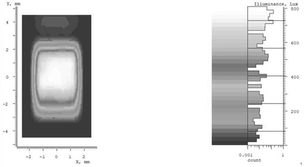
[0004] Therefore, the core bottleneck of the polarization array optical waveguide technology lies in the design and processing of the waveguide lens. The precise control of the film thickness makes most of the widely used waveguide lenses on the market only for S-polarized light waves (the polarization vector is perpendicular to the plane) or P-polarized light waves (the polarization vector is in this plane). As a result, the luminance coupled into the waveguide lens is directly reduced by half, which greatly reduces the light effect, so that the final eye-catching brightness is greatly reduced, which cannot meet the eye-catching brightness requirements for some specific workplaces.
[0005] On the other hand, due to the design requirements of the polarization beam-splitting film array waveguide lens, the optical-mechanical collimation system widely used in the market must use two or more polarization beam-splitting prisms (PBS), which makes the optical-mechanical volume heavier. and higher cost

Method used


Image

  • Optical waveguide near-to-eye display device and augmented reality display equipment
  • Optical waveguide near-to-eye display device and augmented reality display equipment
  • Optical waveguide near-to-eye display device and augmented reality display equipment

Examples


Embodiment Construction

[0036] Reference will now be made in detail to the exemplary embodiments, examples of which are illustrated in the accompanying drawings. When the following description refers to the accompanying drawings, the same numerals in different drawings refer to the same or similar elements unless otherwise indicated. The implementations described in the following exemplary examples do not represent all implementations consistent with the present disclosure. Rather, they are merely examples of apparatuses and methods consistent with aspects of the present disclosure as recited in the appended claims.

[0037] Polarization array waveguide technology realizes image output and exit pupil expansion by using a plurality of semi-transparent and semi-reflective film layers placed in parallel at equal intervals and with a certain splitting ratio in the waveguide lens. The semi-transparent and semi-reflective film layer has angle selectivity. , and arranged in an array. The schematic diagram...


PUM


Abstract

The invention relates to an optical waveguide near-to-eye display device and augmented reality display equipment. The optical waveguide near-to-eye display device comprises an optical-mechanical system, a coupling-in prism, a waveguide substrate and an unpolarized light splitting film array. The optical-mechanical system is used for emitting collimated light to the coupling-in prism; the coupling-in prism is arranged in a coupling-in area of the waveguide substrate and is used for coupling incident light into the waveguide substrate; the waveguide substrate is used for transmitting the light coupled into the waveguide substrate to the unpolarized light splitting film array in a total reflection mode; and the unpolarized light splitting film array is arranged in the coupling-out area of thewaveguide substrate and is used for coupling out the light transmitted to the unpolarized light splitting film array to human eyes. According to the technical scheme, the light effect of a waveguidelens can be greatly improved on the premise of not influencing the brightness uniformity of the final light entering the eyes, and the brightness of the final light entering the eyes is improved.

Description

technical field [0001] The present disclosure relates to the field of augmented reality display technology, in particular to an optical waveguide near-eye display device and an augmented reality display device. Background technique [0002] Augmented reality near-eye display (AR glasses), as a device that combines reality and virtuality, allows users to perform related operations in a semi-virtual environment, which can help humans receive information more easily and better recognize the surrounding environment. It is estimated that it is most likely to replace mobile phones as the next-generation information interaction platform to improve the environment and improve work efficiency. [0003] Optical modules are the core components of AR glasses. At present, the most competitive optical display solution is the optical waveguide solution, and the polarization array optical waveguide solution is the most widely used. Polarization array waveguide technology realizes image out...

Claims


Application Information

Patent Timeline
IPC IPC(8): G02B27/01
CPCG02B27/0172
Inventor 崔海涛李艳钱进雍海波
Owner 谷东科技有限公司
Learn More