Miller clamping device for switching transistors connected in parallel and driver including the same

A switching transistor and transistor technology, applied in the field of Miller clamping devices and drivers, can solve the problems of Miller clamping of switching transistors that cannot be connected in parallel, and achieve the effects of saving circuit costs, improving effects, and reducing equivalent resistance.

Pending Publication Date: 2020-11-27
SANTAK ELECTRONICS SHENZHEN
View PDF0 Cites 5 Cited by
  • Summary
  • Abstract
  • Description
  • Claims
  • Application Information

AI Technical Summary

Problems solved by technology

[0012] Therefore, existing driver ICs cannot perform effective Miller clamping of switching transistors connected in parallel

Method used


Image

  • Miller clamping device for switching transistors connected in parallel and driver including the same
  • Miller clamping device for switching transistors connected in parallel and driver including the same
  • Miller clamping device for switching transistors connected in parallel and driver including the same

Examples


Embodiment Construction

[0041] In order to make the object, technical solution and advantages of the present invention clearer, the present invention will be further described in detail below through specific embodiments in conjunction with the accompanying drawings.

[0042] For the convenience of the following description, the high level and low level defined below are well-known technical concepts or terms in the field of analog circuits or digital circuits, for example, the high level can be a voltage of 5 volts, 12 volts or 24 volts, and the low level Can be a voltage less than 1 volt or a negative voltage lower than logic ground or actual ground voltage.

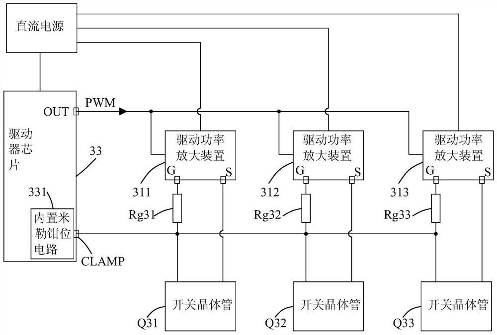
[0043] Figure 4 is a block diagram of a driver for switching transistors connected in parallel according to a preferred embodiment of the present invention. Such as Figure 4 shown, driver 4 with image 3 The drivers shown are basically the same, the difference is that the driver 4 also includes an auxiliary Miller clamp circuit 401, an a...


PUM


Abstract

The present invention provides a Miller clamping device for switching transistors connected in parallel and a driver including the same. The Miller clamping device comprises a driver chip including anoutput terminal for outputting a pulse width modulation signal and a built-in Miller clamping circuit having a Miller clamping terminal; each auxiliary Miller clamping circuit is connected between the gate pole of the corresponding switching transistor and the Miller clamping terminal of the built-in Miller clamping circuit; when the built-in Miller clamping circuit is triggered to be used for Miller clamping, the Miller current generated by the corresponding switching transistor flows to a first direct-current voltage through the corresponding auxiliary Miller clamping circuit. According tothe Miller clamping device, Miller clamping can be carried out on the switching transistors connected in parallel, and the circuit cost is reduced.

Description

technical field [0001] The invention relates to a Miller clamping circuit, in particular to a Miller clamping device for parallel switching transistors and a driver comprising the same. Background technique [0002] Switching transistors (such as IGBTs or MOSFETs) have parasitic Miller capacitances, which cause a very significant Miller effect, that is, when the switching transistor is controlled to be on, the switching transistor is controlled to conduct. The Miller capacitance of the switching transistor connected to a bridge arm increases the voltage at the gate (ie, its control electrode), which may cause the switching transistor to turn on incorrectly. [0003] figure 1 It is a circuit diagram of a driver for a metal oxide semiconductor field effect transistor in the prior art, wherein the driver includes a driver chip 13 and a driving power amplifier 11, which is powered by a DC power supply 12, wherein the output terminal OUT of the driver chip 13 outputs a pulse wid...

Claims


Application Information

Patent Timeline
Patent Type & Authority Applications(China)
IPC IPC(8): H03K17/16H03K17/06
CPCH03K17/16H03K17/06H03K2017/066
Inventor 金东鑫欧阳华奋曹磊李化良郑大为
Owner SANTAK ELECTRONICS SHENZHEN
Why Eureka
Try Eureka