Supercharge Your Innovation With Domain-Expert AI Agents!

Motor temperature control device and method

A technology for controlling device and motor temperature, applied in motor control, electromechanical device, emergency protection circuit device, etc., can solve problems such as motor temperature rise, insulation material damage, motor burn-in, etc. The effect of short-circuit burn-in and automatic cooling in time

Active Publication Date: 2020-12-01
HANGZHOU WEIGUANG ELECTRONICS
View PDF7 Cites 4 Cited by
  • Summary
  • Abstract
  • Description
  • Claims
  • Application Information

AI Technical Summary

Problems solved by technology

[0002] Changes in the operating conditions of the motor and large motor overloads cause the temperature of the motor to rise, which is prone to motor burn-in, bearing damage, insulation material damage, magnetic flux degradation, and even short-circuit fires causing serious accidents
[0003] Although there are similar installations at present, there are some disadvantages. For example, the existing technology is easy to install and usually the temperature sensor is placed between the coils, and there is a certain distance from the coils, so it cannot sense the temperature changes of the coils in time and accurately. This is not conducive to the motor driver to make timely control
In addition, the existing control method is relatively simple. When the temperature exceeds the limit value, the motor will stop working. For some working conditions, there may be many factors for sudden changes in temperature, which may be due to sudden changes in external ambient temperature or sudden changes in ventilation conditions. , these effects will recover in a short time, the motor does not have to stop immediately, it can slow down or continue to observe for a period of time, and then make corresponding controls according to further changes in temperature

Method used


Image

  • Motor temperature control device and method
  • Motor temperature control device and method
  • Motor temperature control device and method

Examples


Embodiment 1

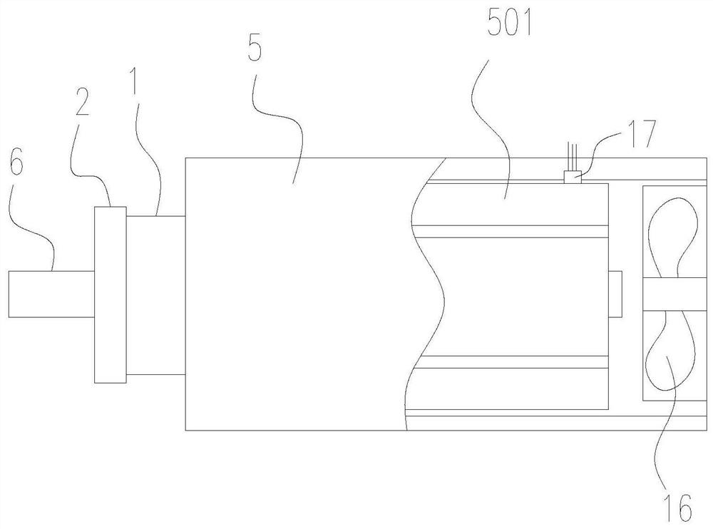
[0028] like figure 1 As shown, a motor temperature control device includes a temperature sensor 17, a motor driver, and a cooling fan 16. The temperature sensor is fixed on the motor 5 housing, and the temperature sensing part of the temperature sensor is in contact with the motor coil 501. The temperature change of the control motor power changes and the rotating speed of cooling fan 16. The cooling fan is arranged on the rear end cover of the motor. The motor may be a servo motor, and the motor driver may be a servo motor driver.

[0029] As a method of motor temperature control: when the measured temperature of the temperature sensor is lower than the first temperature setting value (such as 120°C), the motor runs normally; when the measured temperature rises above the second temperature setting value (such as 130°C), Reduce the current of the motor through the motor driver; when the measured temperature rises above the third temperature setting value (such as 140°C), the...

Embodiment 2

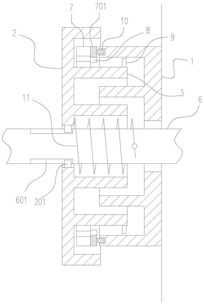
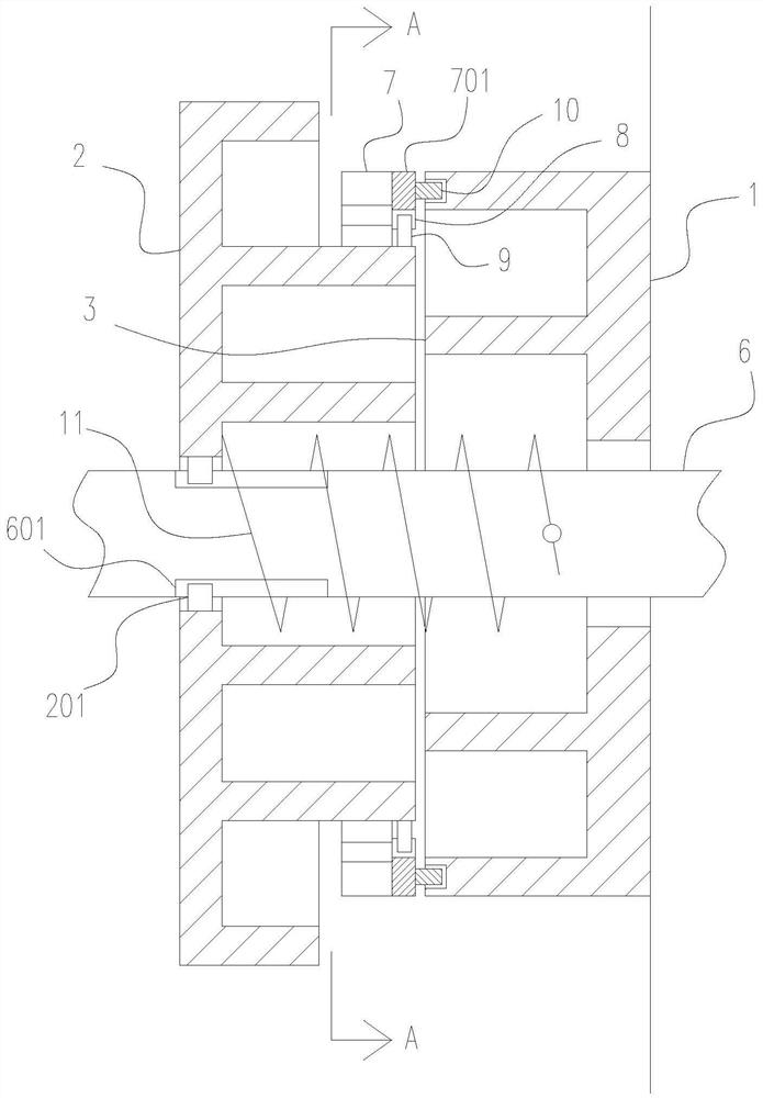
[0032] like figure 2 , 3As shown in , 4, the difference from the above-mentioned embodiment is that a shaft rotating sealing heat dissipation device is provided between the motor shaft and the motor end cover, and the shaft rotating sealing heat dissipation device includes a shaft concentric ring 2 arranged on the rotating shaft 6 And the end concentric ring 1 arranged on the end cover, the coaxial radial staggered interval between the shaft concentric ring and the ring body 3 of the end concentric ring, so as to form a circuitous path of air flow and reduce the entry of dust and impurities from the outside To the gap between the rotating shaft and the end cover, the shaft concentric ring is coaxially slidably arranged on the rotating shaft, the rotating shaft is provided with an axial slide groove 601, and the shaft concentric ring is provided with a slide fit in the axial slide groove Block 201, so that the concentric ring of the shaft can be rotated by the rotating shaft,...

Embodiment 3

[0040] like Figure 5 , 6 As shown, the difference from the above embodiment is that the axial telescopic control device is a shape memory alloy spring 12, the shape memory alloy spring is supported between the concentric ring of the shaft and the rotating shaft, and the concentric ring of the shaft is arranged on the rotating shaft. Position part 14, such as an axial limit snap ring, a supporting spring 13 is supported between the concentric ring limit part of the shaft and the concentric ring of the shaft. When the temperature is higher than the phase transition temperature of the shape memory alloy, the shape memory alloy spring stretches The length overcomes the supporting force of the support spring, so that the concentric ring of the shaft is far away from the concentric ring of the end, so that the inward locking part and the outward locking part are in contact with each other in the direction of rotation. When the temperature is lower than the phase transition temperat...


PUM


Abstract

The invention provides a motor temperature control device and method, and relates to motor equipment. The problem of motor temperature control in the prior art is solved. The invention discloses a motor temperature control device and method. The device comprises a temperature sensor, a motor driver and a cooling fan. The temperature sensor is fixed to the motor shell, the temperature sensing position of the temperature sensor makes contact with or makes close contact with or measures the motor coil, the real-time and actual temperature of the coil can be accurately reflected, it is ensured that motor protection is effective, and the motor driver controls the motor power change and the rotating speed of the cooling fan according to the temperature change of the temperature sensor. The temperature of the coil can be detected in time, the motor driver controls the motor differently according to the temperature of the temperature sensor, so that the temperature of the motor is prevented from being too high, the sealing of the rotating part of the shaft part can be improved by arranging the shaft part rotating sealing heat dissipation device, and automatic heat dissipation can be achieved in time when the temperature rises.

Description

technical field [0001] The invention belongs to the technical field of motors, in particular to a motor temperature control device. Background technique [0002] Changes in the operating conditions of the motor and large motor overloads cause the temperature of the motor to rise, which is prone to motor burnout, damage to bearings, damage to insulating materials, degradation of magnetic flux, and even short-circuit fires causing serious accidents. [0003] Although there are similar installations at present, there are some disadvantages. For example, the existing technology is easy to install. Usually, the temperature sensor is placed between the coils, and there is a certain distance from the coils. It cannot sense the temperature changes of the coils in time and accurately. This is not conducive to the timely control of the motor driver. In addition, the existing control method is relatively simple. When the temperature exceeds the limit value, the motor will stop working...

Claims


Application Information

Patent Timeline
IPC IPC(8): H02K9/06H02K11/25H02P29/60H02P29/64H02P29/028H02P29/032H02H7/085
CPCH02K9/06H02K11/25H02P29/60H02P29/64H02P29/028H02P29/032H02H7/0852H02H7/0858
Inventor 张继生江爱国刘海平吕炳桂冬冬
Owner HANGZHOU WEIGUANG ELECTRONICS
Features
  • R&D
  • Intellectual Property
  • Life Sciences
  • Materials
  • Tech Scout
  • Unparalleled Data Quality
  • Higher Quality Content
  • 60% Fewer Hallucinations
Learn More