Intelligent antenna network calibration method

A calibration method and smart antenna technology, applied in the field of network calibration, can solve problems such as changes in beam shape and power control accuracy, many equipment applications, and low calibration efficiency, and achieve the effects of reducing calibration costs, speeding up calibration efficiency, and strong practicability.

Inactive Publication Date: 2020-12-01
安徽蓝煜电子科技有限公司
View PDF5 Cites 0 Cited by
  • Summary
  • Abstract
  • Description
  • Claims
  • Application Information

AI Technical Summary

Problems solved by technology

In the actual smart antenna system, there are various time-varying errors, such as phase and gain differences introduced by radio frequency channel changes with the environment, device aging, amplitude-frequency phase-frequency characteristic distortion, I/Q imbalance, etc.
These time-varying errors will lead to changes in beam shape and power control accuracy,

Method used


Image

  • Intelligent antenna network calibration method

Examples


Embodiment Construction

[0014] The following will clearly and completely describe the technical solutions in the embodiments of the present invention with reference to the accompanying drawings in the embodiments of the present invention. Obviously, the described embodiments are only some, not all, embodiments of the present invention. Based on the embodiments of the present invention, all other embodiments obtained by persons of ordinary skill in the art without making creative efforts belong to the protection scope of the present invention.

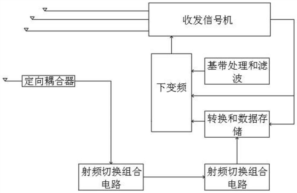
[0015] The present invention provides such as figure 1 A method for calibrating a smart antenna network is shown, including:

[0016] Input the signal into the RF switching combination circuit through the directional coupler;

[0017] Then after down-conversion, baseband processing and filtering, the obtained signal is compared with the reference signal to obtain the channel error;

[0018] Finally, the channel error is fed back to the calibration detection ...


PUM


Abstract

The invention discloses an intelligent antenna network calibration method. The method comprises the following steps: inputting a signal into a radio frequency switching combination circuit through a directional coupler; after down-conversion, baseband processing and filtering, comparing an obtained signal with a reference signal to obtain a channel error; and finally, feeding the channel error back to the calibration detection unit for calibration. The calibration detection unit is composed of a calibration detection plate and a calibration baseband plate, and the calibration detection plate is composed of a radio frequency switch used for channel detection and a transceiver change-over switch. And the calibration baseband board is used for detecting a channel error, generating an error calibration weight and inputting the error calibration weight into the antenna baseband for processing. The method is simple to operate, high in calibration efficiency and low in cost.

Description

technical field [0001] The invention belongs to the technical field of network calibration, and in particular relates to a smart antenna network calibration method. Background technique [0002] Smart antenna is the key technology of TD-SCDMA mobile communication system. Through the beamforming technology based on the smart antenna, the multi-user interference is effectively suppressed and the system capacity is increased. In the actual smart antenna system, there are various time-varying errors, such as phase and gain differences introduced by radio frequency channel changes with the environment, device aging, amplitude-frequency phase-frequency characteristic distortion, and I / Q imbalance. These time-varying errors will lead to changes in beam shape and power control accuracy, thereby reducing system capacity and affecting system performance, so it is necessary to perform online calibration of smart antennas. [0003] The existing smart antenna network calibration method...

Claims


Application Information

Patent Timeline
IPC IPC(8): H04B17/12H04B17/21
CPCH04B17/12H04B17/21
Inventor 尹桂芳任中华陶平
Owner 安徽蓝煜电子科技有限公司
Why Eureka
Try Eureka