Omnidirectional loudspeaker

A loudspeaker, extending technology, applied in the field of loudspeakers, can solve the problems of large load mass, many phase cancellation areas, and increase the sound range, etc., to achieve the effects of various installation forms, preventing sound short-circuits, and improving sensitivity

Active Publication Date: 2020-12-01
王德生
View PDF9 Cites 0 Cited by
  • Summary
  • Abstract
  • Description
  • Claims
  • Application Information

AI Technical Summary

Problems solved by technology

[0003] Existing omnidirectional speakers and speaker systems are mainly divided into several categories: 1) Documents US4472605 and US4665550 describe that two hemispherical diaphragms are placed horizontally Or the vertical diameter is connected through the structure, and the voice coil installed inside drives the diaphragm to vibrate in the opposite direction. The disadvantage is that there is no diaphragm vibration at the equatorial connection position, and standing waves will be formed in some cases. There are 2 drivers, each 2) documents US20110182449A1 and CN106358129B describe that multiple traditional loudspeakers are arranged in a spherical shell or installed in a polyhedral shell in the form of axially pointing to one point, and that multiple loudspeakers work simultaneously to achieve Increase the sound range, but the disadvantage is that the position of discontinuous sound spreads all over the polygonal joints, and there are many phase cancellation areas in the radiation area; 3) Document DE1977002600550 describes that one end of the egg-shaped diaphragm is connected to the voice coil, and the vibration is squeezed by the up and down movement of the voice coil. The diaphragm deforms and vibrates to produce sound. The disadvantage is that the force required to squeeze the diaphragm to produce sound is relatively large. The diameter of the voice coil is often comparable to the radius of the spherical diaphragm. The upper and lower ends do not participate in radiation within a large range of positions, and the supporting magnet becomes an obstacle to radiation. 4) The document US20080008346A1 describes that the voice coil drives the closed diaphragm connected to it to vibrate, and drives the air to vibrate by moving back and forth. The disadvantages are The diaphragm vibrates through tangential extrusion with the air rather than through uniform expansion to drive the air to vibrate. During the vibration, the center and center of gravity of the diaphragm move, which is very different from the way a pulsating ball vibrates
[0004] A common disadvantage of some of the known solutions is that the number of locations where the diaphragm is attached to the support structure is more than two and / or the attachment locations are relative to the radial direction of the diaphragm Girth is too long
A common disadvantage of another part of the known solutions is that the effective radiation area percentage of the surface of the closed hollow three-dimensional body formed by the envelope of the diaphragm is not high enough
Furthermore, a common disadvantage of the known solutions is that the vibration differs greatly from the ideal pulsating ball due to the unfixed center of the diaphragm when it vibrates

Method used


Image

  • Omnidirectional loudspeaker
  • Omnidirectional loudspeaker
  • Omnidirectional loudspeaker

Examples


Embodiment 1

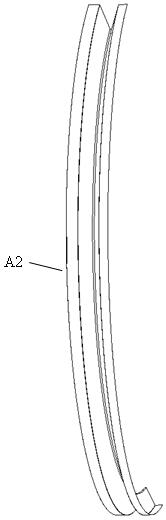
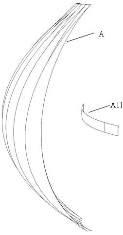
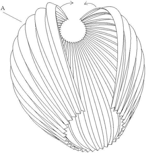
[0061] figure 1 and figure 2 A schematic diagram of Example 1 of the present invention is shown. According to the outer surface profile of the shape of the diaphragm A of the loudspeaker of this embodiment of the present invention, there are only two outer surfaces of closed hollow spheres that are open at both ends of the axial direction; the diaphragm A is partially smooth and partially wrinkled, thereby ensuring its Sound radiation characteristics and structural strength; the diaphragm A of Example 1 is spliced ​​by four non-deformable parts A1 and four deformable parts A2 with the same shape and size and certain rigidity and toughness. Diaphragm A should be as light as possible in order to have minimum inertial mass, preferably, non-deformable part A1 is a thin aluminum sheet with shallower grooves and / or inlaid with other types of materials such as copper to improve strength and vibration characteristics , the deformable part A2 is a rubber sheet.

Embodiment 1

[0062] In Embodiment 1, the cross-sectional area of ​​the opening of each cut-off part of the diaphragm A is less than 1 / 3 of the total area of ​​the outer surface of the diaphragm A, and the projected area of ​​the deformable part A2 on the cross-sectional plane of the opening is smaller than that of the diaphragm A. 1 / 3 of the projected area on this section plane.

[0063] The installation direction of the electromagnetic drive unit B makes the diaphragm A driven by the electromagnetic drive unit B, the non-deformable part A1 drives the deformable part A2, and the center of the diaphragm A as a whole is a fixed reference point, and the uniform expansion and contraction.

[0064] Figure 16 , Figure 17 It shows a schematic diagram of the vibration of the diaphragm A, which is a transverse cross-sectional view of the diaphragm suspended and supported on the central support member C. For the sake of clarity, the deformable part A2 is hidden. It can be seen that the non-deform...

Embodiment 2

[0075] Figure 6 It is an exploded schematic diagram of a part of the hidden part of Embodiment 2 of the present invention. For a clear display, the cable X and the deformable part A2 are hidden. The diaphragm A of the loudspeaker of this embodiment is the outer surface of a closed hollow sphere with a part cut off, and the area corresponding to the axial direction of the cut part of the diaphragm A is a dome-shaped non-deformable part A12, and at the same time Four non-deformable parts A1 are distributed in other areas.

[0076] The loudspeakers of this embodiment cannot be installed in cascade in the axial direction of the central support member C, but since the opening at the upper end is replaced by a dome-shaped non-deformable part A12, the effective radiation area is larger and closer to the pulsation ball source. More than one embodiment 2 can be arranged to be used in cascade perpendicular to the axial direction of the central support member C, or the embodiment 2 can...


PUM


Abstract

The invention relates to an omnidirectional loudspeaker. At least three non-deformable parts of a diaphragm are driven by arranging an electromagnetic driving unit in the diaphragm which forms a closed body with a supporting structure, and the deformable parts of the diaphragm are driven to uniformly expand and contract together, so that the diaphragm radiates sound in a radial and omnidirectionalmanner by taking the center of the whole diaphragm as a fixed reference point.

Description

technical field [0001] The invention relates to a loudspeaker, more specifically to an omnidirectional loudspeaker capable of uniformly radiating sound to the surroundings. Background technique [0002] As the operating frequency increases, the directivity of traditional loudspeakers becomes stronger and stronger. Omnidirectional speakers are one of the powerful ways to expand the range of high-quality listening areas and restore the sound field more realistically. [0003] The existing omnidirectional speakers and speaker systems are mainly divided into several categories: 1) Documents US4472605 and US4665550 describe that two hemispherical diaphragms are connected through structures at horizontal or vertical diameters, and the internally installed voice coil Drive the diaphragm to vibrate in the opposite direction. The disadvantage is that there is no diaphragm vibration at the equatorial connection position. In some cases, standing waves will be formed. There are 2 drive...

Claims


Application Information

Patent Timeline
Patent Type & Authority Applications(China)
IPC IPC(8): H04R1/34
CPCH04R1/345
Inventor 王德生
Owner 王德生
Why Eureka
Try Eureka