
Smoke generating device for induction heating at front end of cigarette

A smoke generating device and induction heating technology, which is applied in the direction of tobacco, etc., can solve the problems of low heat capacity, peculiar smell of cigarettes, and the inability to install temperature sensors directly, and achieve the effect of high degree of dispersion and high airflow dispersion

Pending Publication Date: 2020-12-04
CHINA TOBACCO YUNNAN IND
View PDF0 Cites 8 Cited by
  • Summary
  • Abstract
  • Description
  • Claims
  • Application Information

AI Technical Summary

Problems solved by technology

[0005] 1. The shredded tobacco that is in direct contact with the cigarette or shredded tobacco can be fully toasted, while the shredded tobacco that is a little far from the heating element cannot be toasted sufficiently, and the toasting effect has certain differences on the circumferential cross section of the cigarette. Uniformity;
[0006] 2. The heating appliance itself is small in size and its heat capacity is not high
But at the same time, the problem is that after the tobacco in contact with the heating element is heated several times, the cured tobacco substance will stick to the heating element, which will bring peculiar smell or heating difficulty to the subsequent cigarettes.
Although this kind of charcoal-heated cigarette has the characteristics of lower harm than the existing ordinary cigarettes, the front end of the cigarette is attached with a carbon rod, which not only increases the difficulty of cigarette manufacturing, affects production efficiency, but also causes consumers to ignite the charcoal rod. It takes a long time, it is not easy to ignite, and the charcoal rod may have some disadvantages such as peculiar smell when burning
Similarly, it is difficult to control the charcoal stick after it is ignited. When not smoking, there is also the roasting of the shredded tobacco.
And the end of the charcoal rod is also in direct contact with or relatively close to the shredded tobacco. Therefore, there are the following problems: a small amount of residual shredded tobacco is directly toasted or even critically baked at the end of the charcoal rod.
[0010] 1. Due to the energization of the adjacent surfaces of the heating element, there must be enough space for mutual insulation to prevent short circuits. Therefore, there is a problem that only the air flowing through the surface layer of the heating element can be fully heated;
[0011] 2. The problem of inconvenient temperature measurement and control of the heating element: because the temperature sensor cannot be directly installed on the heating element, and on the path of the air flow, not only is it inconvenient to install and lead wires, but also there are air flow and static time between suction and non-suction. The relative temperature difference is too large, it is difficult to control and determine the problem

Method used


Image

  • Smoke generating device for induction heating at front end of cigarette
  • Smoke generating device for induction heating at front end of cigarette
  • Smoke generating device for induction heating at front end of cigarette

Examples


Embodiment 1

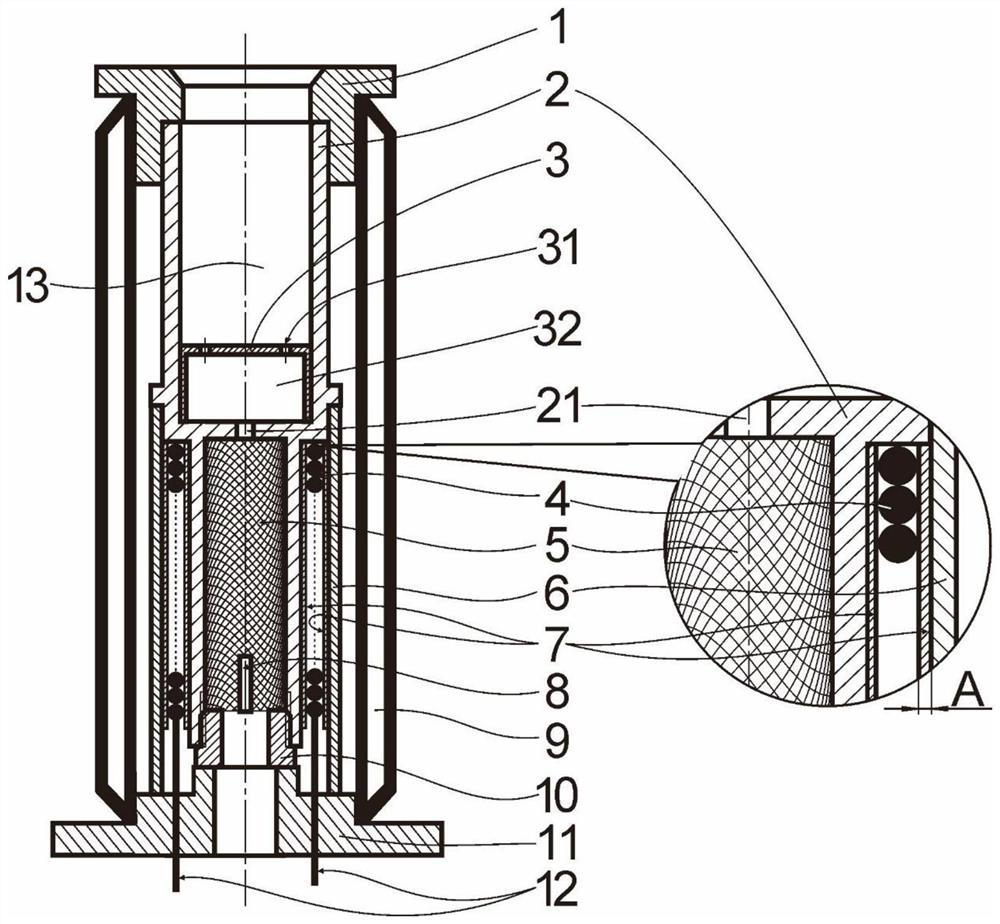
[0064] Such as Figure 1-2 , Embodiment 1 provides a smoking device that is inductively heated at the front end of a cigarette, and the smoking device includes:

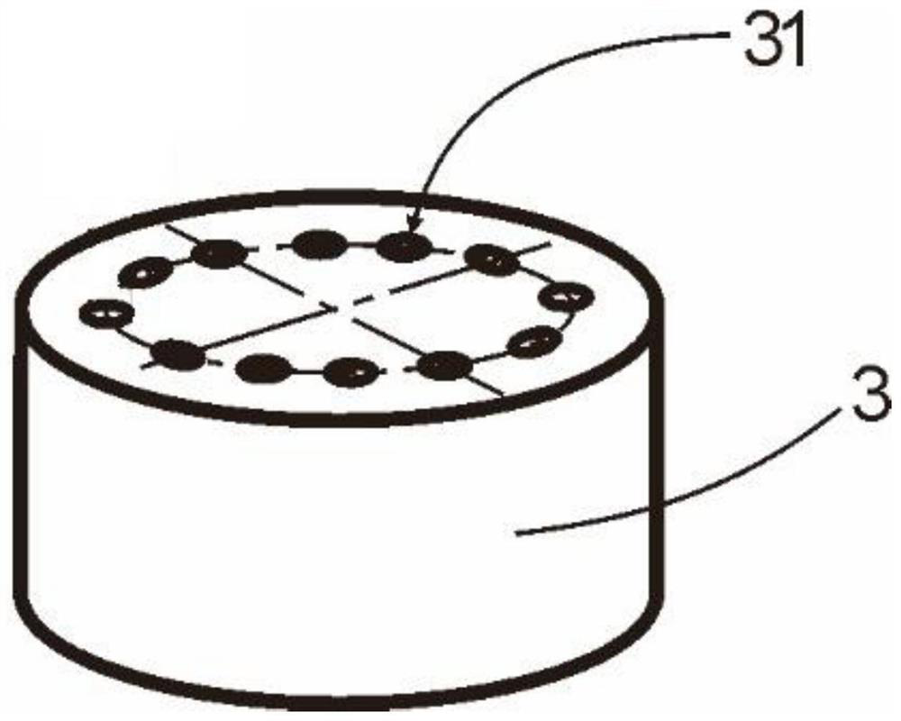
[0065] Socket seat 1, non-metallic hollow heating cup 2, hollow heat spreader 3, induction coil 4, heating element 5, shielding ring 6, heat insulation, insulation isolation layer 7, temperature sensor 8, vacuum insulation tube 9, heat insulation ring 10. Hollow base 11;

[0066] Wherein, the longitudinal section of the heating cup 2 is H-like, and the material is high-precision glass-ceramics, ceramics and other non-metallic materials with high temperature resistance and non-toxicity. The heating cup 2 has an integrated structure, including an upper hollow structure, a lower hollow structure and a baffle between the two, the upper hollow structure includes a cigarette accommodating cavity 13, and the lower hollow structure includes a heating element accommodating cavity, The baffle has a heat collecting hole 21 co...

Embodiment 2

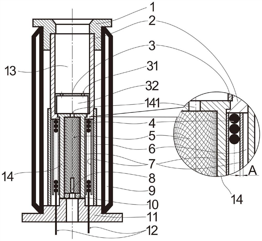
[0082] like image 3 , Embodiment 2 provides a smoking device that is inductively heated at the front end of a cigarette. The difference from Embodiment 1 is that the hollow heating cup 2 is a split structure. The upper part of the hollow heating cup 2 is a hollow tubular structure, and the lower part is a hollow tubular structure 14 with an integrated top plate. thermal hole 21. The upper part and the lower part of the hollow heating cup 2 are clamped.

[0083] The upper hollow tubular structure is made of metal, which is convenient for heat conduction and processing, and the lower hollow tubular structure 14 with a top plate is made of non-metallic material, which is convenient for magnetic conduction.


PUM

PropertyMeasurementUnit
Monofilament diameteraaaaaaaaaa
Diameteraaaaaaaaaa

Abstract

The invention belongs to the field of novel cigarette smoking sets, and particularly relates to a smoke generating device for induction heating at the front end of a cigarette. The smoke generating device comprises a hollow heating cup (2), a heating body (5) and an induction coil (4), A hollow heating cup (2) comprises an upper hollow structure, a lower hollow structure and a baffle between the upper hollow structure and the lower hollow structure; a heating body (5) is arranged in the lower hollow structure, and an induction coil (4) is arranged on the periphery of the heating body (5); andthe heating body (5) is made of ferromagnetic metal and has a structure through which air can pass. According to the invention, the smoke generating device for induction heating at the front end of the cigarette is designed for the first time, and a plurality of airflow channels are formed inside and / or on the surface of the heating body, so that air flowing through the surface of the heating bodycan be quickly and fully heated; the problems that an existing electric heating cigarette is uneven in heating, a carbon heating cigarette is easy to roast and burn and not easy to control, aroma components are insufficient, and smoking feeling is poor are effectively solved.

Description

technical field [0001] The invention belongs to the field of novel cigarette smoking sets, and in particular relates to a smoking device for inductively heating the front end of a cigarette. Background technique [0002] With the improvement of people's health awareness, heat-not-burn cigarettes are more and more popular among smokers because they are less harmful than traditional burn-and-smoke cigarettes. At present, the heating methods of heat-not-burn cigarettes include: contact electric heating, non-contact electric heating, charcoal heating, etc. [0003] Contact electric heating refers to direct contact heating of cigarettes to obtain smoke, which uses various forms of heating appliances such as tubes, needles or plates for electric heating to directly contact with cigarettes or shredded tobacco, at a temperature lower than the ignition point of cigarettes. The cigarette or tobacco is directly contacted and baked to volatilize the aroma components and smoking compone...

Claims


Application Information

Patent Timeline
IPC IPC(8): A24F40/465
CPCA24F40/465
Inventor 吴俊朱东来李廷华李寿波韩熠张霞巩效伟赵伟洪鎏杨强尤俊衡廖晓祥
Owner CHINA TOBACCO YUNNAN IND
Learn More