Powder bed synchronous heating and melting additive manufacturing method

A technology of additive manufacturing and powder bed, which is applied in the field of additive manufacturing, can solve the problems affecting the surface finish of parts, the failure of inner hole forming, and the difficulty of removing inner hole powder, so as to avoid large fluctuations, reduce thermal stress, and high heating efficiency Effect

Active Publication Date: 2020-12-04
TSINGHUA UNIV
View PDF13 Cites 10 Cited by
  • Summary
  • Abstract
  • Description
  • Claims
  • Application Information

AI Technical Summary

Problems solved by technology

[0013] However, if the powder bed temperature is too high, too much powder will be welded to the cross-sectional profile, which will not only af...

Method used


Image

  • Powder bed synchronous heating and melting additive manufacturing method
  • Powder bed synchronous heating and melting additive manufacturing method
  • Powder bed synchronous heating and melting additive manufacturing method

Examples


Embodiment 1

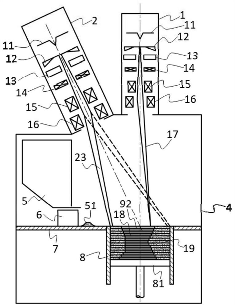
[0064] Such as figure 1 The powder bed synchronous heating and melting process and device shown. Including: vacuum forming chamber 4, working platform 7, forming cylinder 8, piston type lifting device 81, powder feeder 5, powder laying device 6, electron beam emission gathering scanning device 2 for emitting electron beam in heating mode, electron beam emission in melting deposition mode The electron beam emission of the beam focuses the scanning device 1 and a control computer (not shown) as a controller.

[0065] The electron beam emitting and focusing scanning device 2 includes a cathode 11 for generating an electron beam 23 , a grid 12 , an anode 13 , a focusing coil 14 , an astigmatism elimination coil 15 , and a deflection coil 16 . Electron beam emission focusing scanning device 2 emits heating mode electron beam 23 for preheating and heating scanning of the powder bed in the preheating area and heating area, electron beam emitting focusing scanning device 1 emits melt...

Embodiment 2

[0069] Such as Figure 5 The powder bed synchronous heating and melting process and device shown include: vacuum forming chamber 4, working platform 7, forming cylinder 8, piston type lifting device 81, powder feeder 5, powder laying device 6, anti-evaporation device 36, electronic A beam emitting focusing scanning device 2, a laser beam emitting focusing scanning device 3, and a control computer (not shown) as a controller.

[0070] The laser beam emitting and gathering scanning device 3 includes a laser light source 31 that generates laser light and a focusing scanning device 32 connected to the laser light source 31, generates a laser beam 37 that passes through the lead glass 33 and enters the vacuum forming chamber 4, and scans the area of ​​the formed part for sintering and melting powder.

[0071] The vacuum forming chamber 4 provides a vacuum environment for the selective melting process, and a working platform 7 is arranged horizontally in the middle. The powder fee...


PUM

PropertyMeasurementUnit
Poweraaaaaaaaaa
Diameteraaaaaaaaaa
Poweraaaaaaaaaa

Abstract

The invention belongs to the technical field of additive manufacturing, and relates to a powder bed synchronous heating and melting additive manufacturing method which is used for realizing material additive manufacturing under the conditions of a vacuum environment and a high powder bed temperature. According to the method, synchronous electron beam heating is carried out on a non-part section area while selective melting deposition is carried out to form a part section, the powder bed temperature at the non-part section area is kept, large fluctuation of the powder bed temperature is avoided, and it is guaranteed that the staying time of electron beams in unit areas of different positions of a powder bed is equal, so that the energy densities of the electron beams received at the different positions of a preheating area are equal, the temperatures at different positions of the preheating area are uniform, the stability and consistency of the key technological parameter of the powderbed temperature in a powder bed melting technology are enhanced, the thermal stress of the formed part is reduced, the consistency of the performance of the formed part is improved, and conditions arecreated for additive manufacturing of refractory, difficult-to-weld and brittle materials.

Description

technical field [0001] The invention belongs to the technical field of additive manufacturing, and relates to a powder bed synchronous heating and melting additive manufacturing method, which is used to realize material additive manufacturing under vacuum environment and high powder bed temperature conditions. Background technique [0002] The powder bed fusion technology in the additive manufacturing of parts has great advantages in the forming of complex structural parts and the forming of special materials. This process usually uses high-energy electron beams or laser beams as a heat source to sinter or melt materials layer by layer, so that materials are piled up layer by layer. Typical processes include selective laser melting (Selective Laser Melting, SLM) and electron beam selective melting (Electron Beam Selective Melting, EBSM). [0003] Among them, the laser selective melting technology has higher precision and smaller surface roughness. However, since the laser ...

Claims


Application Information

Patent Timeline
IPC IPC(8): B22F3/105B33Y10/00
CPCB33Y10/00Y02P10/25
Inventor 林峰李阳李宏新余业锋张磊
Owner TSINGHUA UNIV
Why Eureka
Try Eureka